Programming Arduino on Industrial Environments:
Course 10 Chapters of General Content [IS.AC001.GC]
#0 HANDY MATERIAL TO DEVELOP AN INDUSTRIAL PROJECT USING ARDUINO
I imagine that you already know what Arduino is, so in this course, we will focus on how to use Arduino boards and Arduino based PLCs in industrial environments to execute projects 30% faster.
Using different simple and free tools you will become a high-performance Arduino programmer, capable to develop an Arduino project. The time in an industrial project is money, so we are going to show you save 30% of your time.
- Check and evaluate the different variables and signals connected to the PLC with a graphical interface.
- Use examples already developed, so you don’t have to start from scratch. (Yes, examples! it is not necessary that you write the full code). There are many valuable examples to develop your projects).
- Use libraries for your standard functions.
(Remember: For us, a PLC works like an individual Arduino board. Our PLCs use original Arduino boards inside it, so you can practice the examples showed on this course using original Arduino boards).
Install the following material on your computer to start the chapter #1 next week.
Using a simple graphical platform you can display the PLC status easily and in a friendly way. You can also use it as a SCADA in your project and you can integrate it into your projects as a Human-Machine-Interface. Simple, easy and free. We recommend using an Open Source platform called PROCESSING. (The Arduino IDE is based on this platform, so you will find it very familiar).
Use the original Arduino IDE to program your PLC. Review the different examples from the Arduino IDE and avoid to have to start your project from scratch. It is necessary to select the Arduino board in the right USB port where the Arduino board is connected to the computer.
To configure the different inputs and outputs from the Industrial Shields PLC is easy.
You can also use the library from GitHub and forget the pinout checking. See how to upload the library from our blog.
Please, answer this Survey will help us to improve the course.
#1 Connect an Arduino board to the laptop
It is necessary to know 2 essentials things:
Using Processing it is available to have a Graphical Interface done easily and simple which let us monitoring and interact with the PLC and controlling all your installation.
The Arduino IDE let us use libraries where calling our standard algorithms and develop a structured program. We encourage you to see the current version of the original Industrial Shields library from GitHub, so you can see how the folders are structured. In the following chapters, we will see how to develop a library and how to call them using the Arduino IDE.
(Remember: Industrial Shields PLCs are working as Original Arduino boards. Our PLCs have original Arduino boards assembled inside. Then, you can practice the course using an Original Arduino board).
Useful Links
Material to do practices
- Arduino Leonardo or Arduino Mega (You also can use an Arduino UNO if you get it).
(The devices used with the Arduino Mega and Arduino Leonardo assembled inside have been: From the Ethernet PLCs; the M-duino21. From the 20I/Os PLC; The
Please, answer this
Survey
and help us to improve the Course.
#2 INPUTS
It is necessary to know some essentials things:
You can do the course practices using an original Arduino board. In fact, our PLCs have an original Arduino board assembled inside, So, it is not necessary to do practices using our devices if you don’t want. You can use an Arduino Leonardo board, which is the board used in our 20I/Os PLCs (they are called:
Connection Alert:
It is important to note that Arduino works at 5Vdc, then you can not connect industrial sensors directly on an Input on the Arduino board because industrial sensors usually work at 24Vdc. On the other hand, all Arduino based PLCs can be connected to an industrial sensor because all digital inputs can run from 5Vdc to 24Vdc.
(Remember: Industrial Shields PLCs are working as Original Arduino boards. Our PLCs have original Arduino boards assembled inside. Then, you can practice the course using an Original Arduino board)
If you need to connect analog sensors, remember that the analog inputs from the Arduino boards work from 0 to 5Vdc. And you can not connect higher voltages. On the other hand in the industry, it is usually to use analog sensors which work at 4-20mA or 0-10Vdc. Then, convert the current signal to voltage is very easy if you use the Ohm formula: V=IxR, you can see an example of how to convert 4-20mA to 0-10Vdc at our blog.
Useful Links:
Material to do practices:
- Arduino Leonardo or Arduino Mega (You also can use an Arduino UNO if you get it).
(The devices used with the Arduino Mega and Arduino Leonardo assembled inside have been: From the Ethernet PLCs; the M-duino21. From the 20I/Os PLC; The
Please, answer this Survey and help us to improve the Course.
#3 OUTPUTS
Basic skills:
You can do the course practices using an original Arduino board. In fact, our PLCs have an original Arduino board assembled inside, So, it is not necessary to do practices using our devices if you don’t want. You can use an Arduino Leonardo board, which is the board used in our 20I/Os PLCs (they are called:
Connection Alert:
The outputs from the PLCs provide Voltaje when the state is defined as a HIGH level. Then it is necessary to keep in mind the polarity of the different types of devices connected to the outputs. The voltage provided from the none Optoisolation outputs is the same voltage connected at the PLC as a powering. It means that if the PLC is powered at 12Vcc the outputs work at 12Vcc and 24Vcc if the power supply is 24Vcc. It is also important to join the negative signal as shown on the PLC. To define the level of the outputs it is necessary to use the sentence: DigitaWrite().
(Remember: Industrial Shields PLCs are working as Original Arduino boards. Our PLCs have original Arduino boards assembled inside. Then, you can practice the course using an Original Arduino board)
The analog outputs are programmed exactly as the PWM outputs. Arduino works at 5Vcc but the outputs from the PLC depends on the Voltage connected to the PLC. The Analog outputs work at 0-10Vdc as standardized on the industry. The analog output resolution is 8 bits then you can configure using the sentence AnalogWrite() a value from 0 to 255.
- Useful Links:
Material to do practices:
- Arduino Leonardo or Arduino Mega (You also can use an Arduino UNO if you get it).
(The devices used with the Arduino Mega and Arduino
Please, answer this Survey and help us to improve the Course.
You have to know some very basic things:
You can practice with an Arduino board. In the different PLCs we use original Arduino boards, for this
Often, when inputs are read in a PLC, their status is stored in a variable. This variable can be used to send its status through some communication system (RS485, RS232, Ethernet, Serial TTL, etc.) or also to perform a series of functions such as filters, working by flanks, counters, etc. To activate an output, it is also common to use a series of variables that will be responsible for defining the state of the output in question.
Work for the student
In this chapter, we are going to make you work. Now you should know how to read a digital input and an analog input. You should also know how to activate a digital output and an analog output. (Remember that the analog outputs are programmed the same as the PWM outputs, although some give you a signal by pulses and the other one gives you an analog signal 0-10Vdc depending on the value that according to the 8bits outputs oscillates between 0-255).
(Remember: For us, a PLC works like an Arduino board. Our PLCs use original Arduino boards, so you can try this course using original Arduino boards).
Useful Links
Material to practice
-
Arduino Leonardo or Arduino Mega (You can also use an Arduino UNO board if you have one).
(The equipment used with the Arduino Mega and Arduino Leonardo boards inside it were: the Ethernet PLC family, the M-duino21 and the basic 20 I / Os PLCs, the
Please, answer this Survey and help us to improve the Course.
#5 VARIABLES I
When reading this chapter you have to take into account a series of points:
You can practice with an Arduino board. In the different PLCs we use original Arduino boards, for this
In this chapter, we tell you some basic notions of the types of variables that we treat in a program. This is important since using the variable of the appropriate type in a project is key to avoid possible problems when operating with these. It also allows you to optimize well the code thing that you will appreciate when you go to use different systems of communication with the equipment (RS485, RS232, Ethernet, Serial TTL, etc) Everything that we will see in this chapter serves you so much for the programming in General, not only for Arduino programming but it is very important to know and know that there are differences between the different types of Variables. And also certain similarities between one or the other so you will not have to feel overwhelmed to see this agenda. With the different chapters, you will see and assimilate the use of one type and another.
Review of the agenda:
In this chapter we are going, apart from watching the video, we recommend that you read the different types of variables that we are dealing with.
In the video, we show you where you can see this information so that very quickly you can review the agenda of this chapter. The objective is that you can identify the different types of variables treated as well as have an idea of when to use one type or another.
(Remember: For
Useful Links:
Material to practice:
- Arduino Leonardo or Arduino Mega (You can also use an Arduino UNO board if you have one).
(The equipment used with the Arduino Mega and Arduino Leonardo boards inside it were: the Ethernet PLC family, the M-duino21 and the basic 20 I / Os PLCs, the
Please, answer this Survey and help us to improve the Course.
#6 VARIABLES II
When reading this chapter you have to take into account a series of points:
You can practice with an Arduino board. In the different PLCs we use original Arduino boards, for this
In this chapter we continue with the types of variables that we treat in a program, where we left it in the previous chapter. This is important since using the variable of the appropriate type in a project is key to avoid possible problems when operating with these. It also allows you to optimize well the code thing that you will appreciate when you go to use different systems of communication with the equipment (RS485, RS232, Ethernet, Serial TTL, etc) Everything what we will see in this chapter serves you so much for the programming in General, not only for Arduino programming but it is very important to know and know that there are differences between the different types of Variables. And also certain similarities between one or the other so you will not have to feel overwhelmed to see this agenda. With the different chapters you will see and assimilate the use of one type and another.
Variables:
It is important to be clear about how different truths are declared and what options we have in each of them. In the final part of the
In the
(Remember: For
Useful Links:
Material to practice:
- Arduino Leonardo or Arduino Mega (You can also use an Arduino UNO board if you have one).
(The equipment used with the Arduino Mega and Arduino Leonardo boards inside it were: the Ethernet PLC family, the M-duino21 and the basic 20 I / Os PLCs, the
Please, answer this Survey and help us to improve the Course.
#7 COMMUNICATIONS
When reading this chapter you have to take into account a series of points:
You can practice with an Arduino board. In the different
In this chapter, we will explain the different types of basic communications available on an Arduino board, as well as the different industrial adaptations to communicate with industrial equipment. The different types of communication enabled in the Arduino-based PLCs are I2C, Serial TTL, RS232, RS485, and SPI, through which we manage to communicate via Ethernet.
Communications:
It is important to be clear about how each type of communication is connected and what can be done in each of these. How many computers can be connected? If you can make a bus or simply allow 2 teams to communicate with each other. etc.
In the video, we show you differences between the communications by Arduino and in the PLCs based on Arduino that allows connecting directly with other industrial equipment. The objective is that you understand that it is more advisable to use depending on the needs so that in the next chapters we will see more in detail each one of these communication systems.
(Remember: For us, a PLC works like an Arduino board, our PLCs use original Arduino boards so you can try this course using original Arduino boards).
Useful links:
Material to practice:
- Arduino Leonardo or Arduino Mega (You can also use an Arduino UNO board if you have one).
(The equipment used with the Arduino Mega and Arduino Leonardo boards inside it were: the Ethernet PLC family, the M-duino21 and the basic 20 I / Os PLCs, the
Please, answer this Survey and help us to improve the Course.
#8 Ethernet
In this chapter, we will see how is the communication protocol Ethernet and how it works in general and with our equipment, taking into account the Arduino IDE perspective. We have to remember that any shield with Ethernet port can be programmed using this protocol, in our devices we have a lot with Ethernet connection like the M-Duino family and many others.
Theoretical Introduction
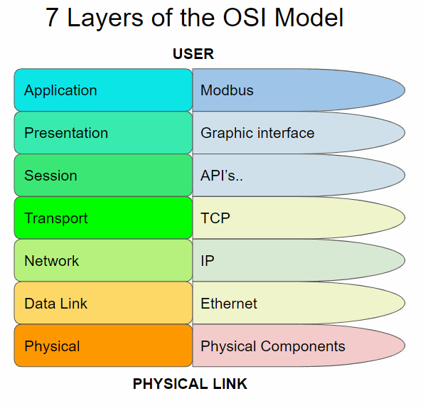
First of all, it is very important to explain the OSI model to understand all the elements which conforms a telecommunication system. The OSI is the Open Systems Interconnection model, and this is a conceptual model that characterizes and standardizes the communication functions of a telecommunication or computing system without regard to its underlying internal structure. Its main goal is the interoperability of diverse communication systems with standard communication protocols. This model is divided into seven different abstraction layers.
Every layer serves the layer above it, and it is served by the layer below it. For instance, a layer that provides error-free communications across a network provides the path required by applications above it, while it calls the next lower layer to send and receive packets that constitute the contents of that path.
The different layers are:
-
Application Layer: is the closest to the user, which means both this and the user interact directly with the software application.
-
Presentation Layer: establishes context between application-layer entities.
-
Session Layer: controls the connections between computers.
-
Transport Layer: provides the functional and procedural means of transferring variable-length data sequences from a source to a destination host, while maintaining the quality of service functions.
-
Network Layer: provides the functional and procedural means of transferring packets from one node to another connected in different networks.
-
Data Link Layer: provides node-to-node data transfer, a link between two directly connected nodes.
-
Physical Layer: is responsible for the transmission and reception of unstructured raw data between a device and a physical transmission medium.
Here, we can see a schematic of the layers :

It is important to take into account that there are two types of Modbus; the Modbus TCP that uses Ethernet and is located in layer 7, and the Modbus 232/485 which uses these protocols and is located in all the layers. We have to consider that, many times, the Network, Data and Physical layers are encompassed as media layers and the others as the host layers.
Now that we are located, we can proceed to the main explication on the video and, if you want to discover more information related to Ethernet, you can check the links than below.
Useful Links
Material to practice
-
Arduino Leonardo or Arduino Mega (You can also use an Arduino UNO board if you have one).
(The equipment used with the Arduino Mega and Arduino Leonardo boards inside it were: the Ethernet PLC family, the M-duino21 and the basic 20 I / Os PLCs, the Ardbox Relay).
Please, answer this
Survey
and help us to improve the Course.
#9 EXAMPLES : CONTROL INPUT-OUTPUT REMOTELY USING ETHERNET
When reading this chapter you have to take into account a series of points:
You can practice with an Arduino board. In the different PLCs we use original Arduino boards, for this reason it is not necessary that you practice with our equipment.
(Remember: For us a PLC works like an Arduino board, our PLCs use original Arduino boards so you can try this course using original Arduino boards).
Introduction:
This is a new chapter about the Arduino programming course for industrial use. In this chapter we will see an example about how to manage the inputs and outputs of an Arduino PLC remotely using Ethernet, related to the previous chapter. So, we will be talking about this example of control and the Ethernet protocol.
There are a lot of different Ethernet protocols; UDP, for example, but the most used is TCP, which we will see a practical example of it. Our programming team developed a new protocol, designed to perform better in our equipment and thinked for our clients, called SimpleComm.
Theoretical explanation:
In this chapter we will see a practical example about how to manage the inputs and outputs of a PLC using Ethernet. We are going to use the TCP protocol to establish this kind of communication but, regarding this, we have to remember the OSI model explained in the previous chapter and, relating this with our specific model, we can see an scheme like this:
Example 1:
This type of communication is based in a master and a slave, you can find more information about this kind of relation in this post -> POST Configuration of RS-485 Protocol on Arduino IDE -Configuration of RS-485 Protocol on Arduino IDE
The practical example that we will see in this chapter is based in two post of our blog, divided in salve and master parts:
-How to use TCP Slave library with Arduino based industrial controller
-Modbus TCP Master with Indsutrial Arduino based PLCs
-How to connect Arduino based PLCs using Modbus TCP/IP
Slave:
In this example, as we saw in the previous paragraphs, the Application layer protocol used is Modbus. First of all we have to see some aspects of this to understand the code in a better way.
| Object type | Access | Size |
| Coil | Read-write | 1bit |
| Discrete input | Read | 1 bit |
| Input register | Read | 16 bits |
| Holding registers | Read-write | 16 bits |
Normally coils a are used to write digital values to an outputs. Discrete inputs are used to read digital inputs. Registers are use to communicate data between the devices and also usually used for analog I/Os.
Requirements
Modbus TCP slave functions
The ModbusTCPSlave module implements the Modbus TCP Slave capabilities.
#include <ModbusTCPSlave.h>

ModbusTCPSlave slave;
The default TCP port is the 502 but you can change it with:
// Set the TCP listening port to 510 instead of 502
ModbusTCPSlave slave(510);
To map the coils, discrete inputs, holding registers and input registers addresses with the desired variables values, the module uses four variables arrays:
bool coils[NUM_COILS];
bool discreteInputs[NUM_DISCRETE_INPUTS];
uint16_t holdingRegistesr[NUM_HOLDING_REGISTERS];
uint16_t inputRegisters[NUM_INPUT_REGISTERS];
The lengths of these arrays depend on the application and the registers usages. Obviously, the names of the arrays also depend on your preferences.
To associate the registers arrays with the library it is possible to use these functions in the setup:
slave.setCoils(coils, NUM_COILS);
slave.setDiscreteInputs(discreteInputs, NUM_DISCRETE_INPUTS);
slave.setHoldingRegisters(holdingRegisters, NUM_HOLDING_REGISTERS);
slave.setInputRegisters(inputRegisters, NUM_INPUT_REGISTERS);
It is not required to have all kind of registers mapping to work, only the used by the application.
To start the ModbusTCP server, call the begin function after the registers mapping. It is also possible to call the beginfunction before the registers mapping. Remember to begin the Ethernet before the ModbusTCPSlave object in the setup.
// Init the Ethernet
Ethernet.begin(mac, ip);

// Init the ModbusTCPSlave object
slave.begin();
At this time the ModbusTCP server is running and the only important thing to do is to update the ModbusTCPSlave object often in the loop function, and tret the registers mapping values to update variables, inputs and outputs.
// Update discrete inputs and input registers values
discreteInputs[0] = digitalRead(I0_7);
inputRegisters[0] = analogRead(I0_0);
// ...

// Update the ModbusTCPSlave object
slave.update();

// Update coils and holding registers
digitalWrite(Q0_0, coils[0]);
// ...
Example software for Arduino based automation controller
/*
   Copyright (c) 2018 Boot&Work Corp., S.L. All rights reserved
   This program is free software: you can redistribute it and/or modify
   it under the terms of the GNU Lesser General Public License as published by
   the Free Software Foundation, either version 3 of the License, or
   (at your option) any later version.
   This program is distributed in the hope that it will be useful,
   but WITHOUT ANY WARRANTY; without even the implied warranty of
   MERCHANTABILITY or FITNESS FOR A PARTICULAR PURPOSE.  See the
   GNU Lesser General Public License for more details.
   You should have received a copy of the GNU Lesser General Public License
   along with this program.  If not, see <http://www.gnu.org/licenses/>.
 */
#include <ModbusTCPSlave.h>
#if defined(MDUINO_PLUS)
#include <Ethernet2.h>
#else
#include <Ethernet.h>
#endif
// Ethernet configuration values
uint8_t mac[] = { 0xDE, 0xAD, 0xBE, 0xEF, 0xFE, 0xEE };
IPAddress ip(10, 10, 10, 4);
int port = 502;
// Modbus registers mapping
// This example uses the M-Duino21+ mapping
int digitalOutputsPins[] = {
#if defined(PIN_Q0_4)
  Q0_0, Q0_1, Q0_2, Q0_3, Q0_4,
#endif
};
int digitalInputsPins[] = {
#if defined(PIN_I0_6)
  I0_0, I0_1, I0_2, I0_3, I0_4, I0_5, I0_6,
#endif
};
int analogOutputsPins[] = {
#if defined(PIN_A0_7)
  A0_5, A0_6, A0_7,
#endif
};
int analogInputsPins[] = {
#if defined(PIN_I0_12)
  I0_7, I0_8, I0_9, I0_10, I0_11, I0_12,
#endif
};
#define numDigitalOutputs int(sizeof(digitalOutputsPins) / sizeof(int))
#define numDigitalInputs int(sizeof(digitalInputsPins) / sizeof(int))
#define numAnalogOutputs int(sizeof(analogOutputsPins) / sizeof(int))
#define numAnalogInputs int(sizeof(analogInputsPins) / sizeof(int))
bool digitalOutputs[numDigitalOutputs];
bool digitalInputs[numDigitalInputs];
uint16_t analogOutputs[numAnalogOutputs];
uint16_t analogInputs[numAnalogInputs];
// Define the ModbusTCPSlave object
ModbusTCPSlave modbus(port);
////////////////////////////////////////////////////////////////////////////////////////////////////
void setup() {
  Serial.begin(9600UL);
  // Init variables, inputs and outputs
  for (int i = 0; i < numDigitalOutputs; ++i) {
    digitalOutputs[i] = false;
    digitalWrite(digitalOutputsPins[i], digitalOutputs[i]);
  }
  for (int i = 0; i < numDigitalInputs; ++i) {
    digitalInputs[i] = digitalRead(digitalInputsPins[i]);
  }
  for (int i = 0; i < numAnalogOutputs; ++i) {
    analogOutputs[i] = 0;
    analogWrite(analogOutputsPins[i], analogOutputs[i]);
  }
  for (int i = 0; i < numAnalogInputs; ++i) {
    analogInputs[i] = analogRead(analogInputsPins[i]);
  }
  // Init Ethernet
  Ethernet.begin(mac, ip);
  Serial.println(Ethernet.localIP());
  // Init ModbusTCPSlave object
  modbus.begin();
  modbus.setCoils(digitalOutputs, numDigitalOutputs);
  modbus.setDiscreteInputs(digitalInputs, numDigitalInputs);
  modbus.setHoldingRegisters(analogOutputs, numAnalogOutputs);
  modbus.setInputRegisters(analogInputs, numAnalogInputs);
}
////////////////////////////////////////////////////////////////////////////////////////////////////
void loop() {
  // Update inputs
  for (int i = 0; i < numDigitalInputs; ++i) {
    digitalInputs[i] = digitalRead(digitalInputsPins[i]);
  }
  for (int i = 0; i < numAnalogInputs; ++i) {
    analogInputs[i] = analogRead(analogInputsPins[i]);
  }
  // Process modbus requests
  modbus.update();
  // Update outputs
  for (int i = 0; i < numDigitalOutputs; ++i) {
    digitalWrite(digitalOutputsPins[i], digitalOutputs[i]);
  }
  for (int i = 0; i < numAnalogOutputs; ++i) {
    analogWrite(analogOutputsPins[i], analogOutputs[i]);
  }
}
Referral
M-Duino controller family Tools40 library installed
Master:
Now, taking into account the same Modbus information that we saw in the Slave part and the same Requirements, we are going to see the master part:
Modbus TCP master functions
The functions to read and write slave values are:
readCoils(client, slave_address, address, quantity);
readDiscreteInputs(client, slave_address, address, quantity);
readHoldingRegisters(client, slave_address, address, quantity);
readInputRegisters(client, slave_address, address, quantity);
writeSingleCoil(client, slave_address, address, value);
writeSingleRegister(client, slave_address, address, value);
writeMultipleCoils(client, slave_address, address, values, quantity);
writeMultipleRegisters(client, slave_address, address, values, quantity);
Where
clientis the EthernetClient connected to the slave.slave_addressis the Modbus TCP slave address.addressis the coil, digital input, holding register or input register address. Usually this address is the coil, digital input, holding register or input register number minus 1: the holding register number40009has the address8.quantityis the number of coils, digital inputs, holding registers or input registers to read/write.valueis the given value of the coil or holding registers on a write operation. Depending on the function the data type changes. A coil is represented by aboolvalue and a holding register is represented by auint16_tvalue.
On a multiple read/write function the address argument is the first element address. On a multiple write function the valuesargument is an array of values to write.
It is important to notice that these functions are non-blocking, so they don't return the read value. They return true or falsedepending on the current module state. If there is a pending Modbus request or the client is not connected, they return false.
// Read 5 holding registers from address 0x24 of slave with address 0x10if (master.readHoldingRegisters(client, 0x10, 0x24, 5)) {
	// OK, the request is being processed
} else {
	// ERROR, the master is not in an IDLE state
}
There is the available() function to check for responses from the slave.
ModbusResponse response = master.available();
if (response) {
	// Process response
}
The ModbusResponse implements some functions to get the response information:
hasError();
getErrorCode();
getSlave();
getFC();
isCoilSet(offset);
isDiscreteInputSet(offset);
isDiscreteSet(offset);
getRegister(offset);
ModbusResponse response = master.available();
if (response) {
	if (response.hasError()) {
		// There is an error. You can get the error code with response.getErrorCode()
	} else {
		// Response ready: print the read holding registers
		for (int i = 0; i < 5; ++i) {
			Serial.println(response.getRegister(i);
		}
	}
}
The possible error codes are:
                            0x01 ILLEGAL FUNCTION
0x02 ILLEGAL DATA ADDRESS
0x03 ILLEGAL DATA VALUE
0x04 SERVER DEVICE FAILURE
Software
After seeing the bases of the Modbus TCP Master library we can proceed to develop a code to communicate with another Modbus device in our network. In this code is showed how to read registers and how to write coils from another Modbus TCP/IP slave. This example will write random numbers to digital coils every second and also will read 6 values from the slave every 500 milliseconds.
/*
   Copyright (c) 2018 Boot&Work Corp., S.L. All rights reserved
   This program is free software: you can redistribute it and/or modify
   it under the terms of the GNU Lesser General Public License as published by
   the Free Software Foundation, either version 3 of the License, or
   (at your option) any later version.
   This program is distributed in the hope that it will be useful,
   but WITHOUT ANY WARRANTY; without even the implied warranty of
   MERCHANTABILITY or FITNESS FOR A PARTICULAR PURPOSE.  See the
   GNU Lesser General Public License for more details.
   You should have received a copy of the GNU Lesser General Public License
   along with this program.  If not, see <http://www.gnu.org/licenses/>.
 */
#include <ModbusTCPMaster.h>
#if defined(MDUINO_PLUS)
#include <Ethernet2.h>
#else
#include <Ethernet.h>
#endif

// Ethernet configuration values
uint8_t mac[] = { 0xDE, 0xAD, 0xBE, 0xEF, 0xFE, 0xED };
IPAddress ip(10, 10, 10, 3);
IPAddress slaveIp(10, 10, 10, 4);
uint16_t slavePort = 502;

// Define the ModbusTCPMaster object
ModbusTCPMaster modbus;

// Ethernet client object used to connect to the slave
EthernetClient slave;
uint32_t lastSentTime = 0UL;
uint32_t lastSentTimeReadInputs = 0UL;

////////////////////////////////////////////////////////////////////////////////////////////////////
void setup() {
  Serial.begin(9600UL);
  // Begin Ethernet
  Ethernet.begin(mac, ip);
  Serial.println(Ethernet.localIP());
  // NOTE: it is not necessary to start the modbus master object
}

////////////////////////////////////////////////////////////////////////////////////////////////////
void loop() {
  // Connect to slave if not connected
  // The ethernet connection is managed by the application, not by the library
  // In this case the connection is opened once
  if (!slave.connected()) {
    slave.stop();
    slave.connect(slaveIp, slavePort);
    if (slave.connected()) {
      Serial.println("Reconnected");
    }
  }
  // Send a request every 1000ms if connected to slave
  if (slave.connected()) {
    if (millis() - lastSentTime > 1000) {
      // Set random values
      bool values[5];
      for (int i = 0; i < 5; ++i) {
        values[i] = random() & 0x01;
      }
      // Send a Write Multiple Coils request to the slave with address 31
      // It requests for setting 5 coils starting in address 0
      // IMPORTANT: all read and write functions start a Modbus transmission, but they are not
      // blocking, so you can continue the program while the Modbus functions work. To check for
      // available responses, call modbus.available() function often.
      if (!modbus.writeMultipleCoils(slave, 31, 0, values, 5)) {
        // Failure treatment
        Serial.println("Request fail");
      }
      lastSentTime = millis();
    }
    // Check available responses often
    if (modbus.isWaitingResponse()) {
      ModbusResponse response = modbus.available();
      if (response) {
        if (response.hasError()) {
          // Response failure treatment. You can use response.getErrorCode()
          // to get the error code.
          Serial.print("Error ");
          Serial.println(response.getErrorCode());
        } else {
          Serial.println("Done");
        }
      }
    }

    if (millis() - lastSentTimeReadInputs > 500) {
      // Send a Read Input Registers request to the slave with address 31
      // It requests for 6 registers starting at address 0
      // IMPORTANT: all read and write functions start a Modbus transmission, but they are not
      // blocking, so you can continue the program while the Modbus functions work. To check for
      // available responses, call master.available() function often.
      if (!modbus.readInputRegisters(slave, 31, 0, 6)) {
        // Failure treatment
      }
      lastSentTimeReadInputs = millis();
    }

    if (modbus.isWaitingResponse()) {
      ModbusResponse response = modbus.available();
      if (response) {
        if (response.hasError()) {
          // Response failure treatment. You can use response.getErrorCode()
          // to get the error code.
        } else {
          // Get the input registers values from the response
          Serial.print("Input registers values: ");
          for (int i = 0; i < 6; ++i) {
            Serial.print(response.getRegister(i));
            Serial.print(',');
          }
          Serial.println();
        }
      }
    }
  }
}
Example 2:
Following the previous Slave part of the example and, changing the Master's code a little bit in order to make it more interactive with the user, here we have another example:
Application Architecture
M-Duino master has a an interactive serial menu that allow the user to control the application. The menu has 6 options. The first four options are to control two outputs of the slave, the fifth option is to get the analog inputs or registers from the slave and the last option, sixth, is to get the digital inputs or discrete inputs from the slave.
We use writeSingleCoil(), readInputRegisters() and readDiscreteInputs() functions to communicate to the slave. Then just executing a short for loop depending of which message we have sent, we read the values using response.getRegister() or response.isDiscreteInputSet().
The rest of the code is just Ethernet configurations and Serial commands to debug and make the application more interactive
Software
/*
   Copyright (c) 2018 Boot&Work Corp., S.L. All rights reserved
   This program is free software: you can redistribute it and/or modify
   it under the terms of the GNU Lesser General Public License as published by
   the Free Software Foundation, either version 3 of the License, or
   (at your option) any later version.
   This program is distributed in the hope that it will be useful,
   but WITHOUT ANY WARRANTY; without even the implied warranty of
   MERCHANTABILITY or FITNESS FOR A PARTICULAR PURPOSE.  See the
   GNU Lesser General Public License for more details.
   You should have received a copy of the GNU Lesser General Public License
   along with this program.  If not, see <http://www.gnu.org/licenses/>.
 */
#include <ModbusTCPMaster.h>
#if defined(MDUINO_PLUS)
#include <Ethernet2.h>
#else
#include <Ethernet.h>
#endif
// Ethernet configuration values
uint8_t mac[] = { 0xDE, 0xAD, 0xBE, 0xEF, 0xFE, 0xED };
IPAddress ip(10, 10, 10, 3);
IPAddress slaveIp(10, 10, 10, 4);
uint16_t slavePort = 502;
// Define the ModbusTCPMaster object
ModbusTCPMaster modbus;
//
bool registerSet = 0;
bool discreteSet = 0;
// Ethernet client object used to connect to the slave
EthernetClient slave;
uint32_t lastSentTime = 0UL;
uint32_t lastSentTimeReadInputs = 0UL;
////////////////////////////////////////////////////////////////////////////////////////////////////
void setup() {
  Serial.begin(9600UL);
  // Begin Ethernet
  Ethernet.begin(mac, ip);
  Serial.println(Ethernet.localIP());
  // NOTE: it is not necessary to start the modbus master object
  mainUI();
}
////////////////////////////////////////////////////////////////////////////////////////////////////
void loop() {
  // Connect to slave if not connected
  // The ethernet connection is managed by the application, not by the library
  // In this case the connection is opened once
  if (!slave.connected()) {
    Serial.println("Slave not connected");
    slave.stop();
    slave.connect(slaveIp, slavePort);
    if (slave.connected()) {
      Serial.println("Reconnected");
    }
  }
  // Send a request every 1000ms if connected to slave
  if (slave.connected()) {
    //Serial.println("Slave connected");
  if (Serial.available()) {
      byte chosenOption= Serial.read();
  bool value;
  byte address;
  switch(chosenOption){
      case '1': //set Q0_0 to high
          value = 1;
          address = 0;
          if (!(modbus.writeSingleCoil(slave, 0, address, value))) {
            // Failure treatment
            Serial.println("Request fail");
          }
          Serial.println("Q0_0 set to HIGH");
          break;
      case '2': //set Q0_0 to low
          value = 0;
          address = 0;
          if (!(modbus.writeSingleCoil(slave, 0, address, value))) {
            // Failure treatment
            Serial.println("Request fail");
          }
          Serial.println("Q0_0 set to LOW");
          break;
      case '3': //set Q0_1 to high
          value = 1;
          address = 1;
          if (!(modbus.writeSingleCoil(slave, 0, address, value))) {
            // Failure treatment
            Serial.println("Request fail");
          }
          Serial.println("Q0_1 set to HIGH");
          break;
      case '4':
          value = 0;
          address= 1;
          if (!(modbus.writeSingleCoil(slave, 0, address, value))) {
            // Failure treatment
            Serial.println("Request fail");
          }
          Serial.println("Q0_1 set to LOW");
          break;
      case '5':
          if (!modbus.readInputRegisters(slave, 0, 0, 6)) {
            // Failure treatment
            Serial.println("Error requesting registers");
          }else{registerSet = true;}
          break;
      case '6':
          if (!modbus.readDiscreteInputs(slave, 0, 0, 7)) {
          // Failure treatment
          Serial.println("Error requesting discrete input");
          }else{discreteSet = true;}
          break;
  }
  mainUI();
    }
    if (modbus.isWaitingResponse()) {
      ModbusResponse response = modbus.available();
      if (response) {
        if (response.hasError()) {
          // Response failure treatment. You can use response.getErrorCode()
          // to get the error code.
        }else if (registerSet){
          // Get the input registers values from the response
          Serial.print("Input registers values: ");
          for (int i = 0; i < 6; ++i) {
            Serial.print(response.getRegister(i));
            Serial.print(',');
          }
          registerSet = false;
        } else if(discreteSet) {
          // Get the input registers values from the response
          Serial.print("Input discrete values: [");
          for (int i = 0; i < 7; ++i) {
            Serial.print(response.isDiscreteInputSet(i));
            Serial.print(',');
          }
          Serial.println(']');
          discreteSet = false;
        }
      }
    }
  }
}
////////////////////////////////////////////////////////////////////////////////////////////////////
void mainUI(){
    Serial.println("********************Modbus Test*********************");
    Serial.println("Chose an option:");
    Serial.println("1. Set Q0_0 to HIGH");
    Serial.println("2. Set Q0_0 to LOW");
    Serial.println("3. Set Q0_1 to HIGH");
    Serial.println("4. Set Q0_1 to LOW");
    Serial.println("5. Print slave input analog values");
    Serial.println("6. Print slave input digital values");
    Serial.println("****************************************************");
}
Useful links:
Material to practice:
- Arduino Leonardo or Arduino Mega (You can also use an Arduino UNO board if you have one).
(The equipment used with the Arduino Mega and Arduino Leonardo boards inside it were: the Ethernet PLC family, the M-duino21 and the basic 20 I / Os PLCs, the Ardbox Relay).
Please, answer this Survey and help us to improve the Course.
#10 Serial TTL, RS232, RS485
Communications in Arduino’s PLC is one of the most outstanding points to consider because is one of their strengths and, related to this, there are so many communication protocols. In this chapter, we are going to see three different types of the main communication protocols; Serial TTL, RS-232 and RS-485.
Serial TTL is a Serial kind of TTL (Transistor-Transistor Logic) communication. TTL is a logic family from bipolar junction transistors. These transistors perform the logic and the amplifying function too.
RS-232 is another standard for serial communication transmission of data. It formally defines signals connecting between DTE (data terminal equipment) such as a computer terminal, and a DCE (data circuit--terminating equipment or data communication equipment), such as a modem.
RS-485 is, one more time, a standard for serial communication systems in which electrical signaling is balanced and multipoint systems are supported. Digital communications networks implementing the standard can be used effectively over long distances and in electrically noisy environments. Multiple receivers may be connected to such a network in a linear, multidrop bus.
With the information shown in this introduction, we can proceed to watch the video.
Now that we are located, we can proceed to the main explication on the video and, if you want to discover more information related to Ethernet, you can check the links than below.
Useful Links
Material to practice
-
Arduino Leonardo or Arduino Mega (You can also use an Arduino UNO board if you have one).
(The equipment used with the Arduino Mega and Arduino Leonardo boards inside it were: the Ethernet PLC family, the M-duino21 and the basic 20 I / Os PLCs, the Ardbox Relay).
Please, answer this
Survey
and help us to improve the Course.