Detalles Técnicos
M-DUINO PLC Arduino Ethernet 57R I/Os Relay/Analog/Digital PLUS WIFI
VOLVER AL PRODUCTOInstalación Inicial
ARDUINO IDE
Arduino IDE es la plataforma original para programar placas Arduino. Esta aplicación multiplataforma está disponible en Windows, macOS y Linux y bajo la Licencia Pública General GNU. Arduino IDE admite la estructuración de código C y C ++.
Industrial Shields recomienda usar Arduino IDE para programar PLC basados en Arduino, pero cualquier software compatible con Arduino es compatible con los controladores Industrial Shields.
Aparte de eso, Industrial Shields brinda la posibilidad de seleccionar su PLC basado en Arduino en su IDE de Arduino y compilar sus bocetos para los diferentes PLC.
Descargue el IDE de Arduino 1.8.6:
POWER SUPPLY
Todos los PLC basados en Arduino se pueden alimentar entre 12-24 V. Tanto la familia M-Duino como la familia Ardbox, tienen un consumo entre 700mA y 1500mA.
Por lo tanto, la fuente de alimentación recomendada es de 2 A o superior. Cualquier fuente de alimentación industrial será una buena opción para alimentarlos.
RECUERDE: Las unidades de salida están diseñadas para funcionar entre 12-24V. Simplemente alimentándolos con el USB, la unidad no podrá realizar sus funciones. El USB es solo para programar los PLC, no para alimentarlos.
Si por alguna razón desea utilizar una fuente de alimentación inferior a 1,5A, póngase en contacto con el soporte técnico de Industrial Shields para asegurarse de que su sistema completará sus funcionalidades sin ningún problema de energía.
A continuación se muestra un diagrama sencillo para ver cómo alimentar cualquier unidad Industrial Shields.

INTERRUPTOR
Nuestras tablas tienen la nomenclatura que se muestra a continuación:

La placa de comunicación (zona A) es compartida con toda la familia M-Duino, por esta razón puede ser que algunos interruptores no tengan funcionalidad o que su posición no esté relacionada en su unidad. En la siguiente tabla se indica qué interruptores están relacionados con la unidad y su funcionalidad:
Zona A Interruptor Superior Izquierdo:

SCL/I2.1: Elegir entre SCL o la entrada I2.1. Si este interruptor está en ON, habilita la entrada I2.1 y deshabilita el SCL. Si este interruptor está en OFF, habilita SCL y deshabilita I2.1.
SDA/I2.0: Elegir entre SDA o la entrada I2.0. Si este interruptor está en ON, habilita la entrada I2.0 y deshabilita el SDA. Si este interruptor está en OFF, habilita SDA y deshabilita I2.0.
RX1/I1.1: Elegir entre RX1 o la entrada I1.1. Si este interruptor está en ON, habilita la entrada I1.1 y deshabilita el RX1. Si este interruptor está en OFF, habilita RX1 y deshabilita I1.1.
TX1/I1.0: Elegir entre TX1 o la entrada I1.0. Si este interruptor está en ON, habilita la entrada I1.0 y deshabilita el TX1. Si este interruptor está en OFF, habilita TX1 y deshabilita I1.0.
Pin 3/I0.1: Elegir entre el Pin 3 o la entrada I0.1. Si este interruptor está en ON, habilita la entrada I0.1 y deshabilita el Pin 3. Si este interruptor está en OFF, habilita el Pin 3 y deshabilita I0.1.
Pin 2 /I0.0: Elegir entre el Pin 2 o la entrada I0.0. Si este interruptor está en ON, habilita la entrada I0.0 y deshabilita el Pin 2. Si este interruptor está en OFF, habilita el Pin 2 y deshabilita I0.0.
D53(SD): Si este interruptor está APAGADO, habilita la selección de chip de la toma microSD y deshabilita Q2.0. Si este interruptor está en ON, habilita la salida Q2.0. Si el interruptor está en modo ON, no se puede usar la microSD.
FD RS-485 HD: Elegir entre (FD) o (HD). Si este interruptor está en ON, habilita la opción Half Duplex (HD) y deshabilita el (FD). Si este interruptor está en OFF, habilita Full Duplex (FD) y deshabilita (HD).
Zona A Izquierda Debajo del Interruptor:

NC : No conectado. Este interruptor no está conectado a nada, no importa si está en modo ENCENDIDO o APAGADO.
NC : No conectado. Este interruptor no está conectado a nada, no importa si está en modo ON o OFF
RTC (SDA): Este interruptor permite que la comunicación se comunique con el RTC mediante I2C. Tener este interruptor en modo ON activa esta comunicación, mientras que si está en modo OFF desactiva el I2C para llegar al RTC.
RTC (SCL): Este interruptor permite que la comunicación se comunique con el RTC mediante I2C. Tener este interruptor en modo ON activa esta comunicación, mientras que si está en modo OFF desactiva el I2C para llegar al RTC.
Zona B Relay:

|
INTERRUPTOR |
ON | OFF |
| 4 | NC | NC |
| 3 | Q0.2 | A0.2 |
| 2 | Q0.1 | A0.1 |
| 1 | Q0.0 | A0.0 |
Zona C Relay:

|
INTERRUPTOR |
ON | OFF |
| 4 | NC | NC |
| 3 | Q1.2 | A1.2 |
| 2 | Q1.1 | A1.1 |
| 1 | Q1.0 | A1.0 |
Zona D Relay:

|
INTERRUPTOR |
ON | OFF |
| 4 | NC | NC |
| 3 | NC | NC |
| 2 | Q2.1 | A2.1 |
| 1 | Q2.0 | A2.0 |
Para el blindaje del relé, si un interruptor está en ON, solo puede actuar como salida digital. Si está en OFF, solo puede actuar como una salida analógica.
Si se desea utilizar una salida digital, el pin debe estar en ON y el pin que proporcionará esta salida digital se representa con QX.X, siendo X cualquier número de las tablas anteriores.
Si se desea utilizar una salida analógica, el pin debe estar en OFF y el pin que proporcionará esta salida analógica se representa con AX.X, siendo X cualquier número de las tablas anteriores.
Entradas y Salidas
ENTRADAS ANALÒGICAS
La variación de voltaje entre –Vcc (o GND) y + Vcc, puede tomar cualquier valor. Una entrada analógica proporciona una medición codificada en forma de valor digital con un número de N bits. En las E / S digitales y analógicas hay autoaislamiento, por lo que es posible conectarlas a una fuente de alimentación diferente a la de 24 V.
Entradas: (12x) Analógica (0-10Vdc) / Digital (5-24Vdc) configurable por software.
Know more about Analog Inputs.
TYPICAL CONNECTION

ENTRADAS DIGITALES
Variación de tensión de –Vcc (o GND) a + Vcc, sin valores intermedios. Dos estados: 0 (-Vcc o GND) y 1 (+ Vcc). En las E / S digitales y analógicas hay autoaislamiento, por lo que es posible conectarlas a una fuente de alimentación diferente a la de 24 V.
Entradas digitales nos proporciona entrada PNP.
Entradas: (6x) Digital Aislado (5-24Vdc) que puede funcionar como interrupción INT (7-24Vdc).
Know more about Digital Inputs.
TYPICAL CONNECTION
- Entrada digital aislada

- Entrada digital sin aislamiento

ENTRADAS DE INTERRUPCIÓN
Interrumpir la rutina del servicio. Mecanismo que permite asociar una función con la ocurrencia de un evento en particular. Cuando ocurre el evento, el procesador sale inmediatamente del flujo normal del programa y ejecuta la función ISR asociada ignorando cualquier otra tarea.
Entradas: (6x) Entradas de interrupción (5-24Vdc). “Puede funcionar como entrada digital (24Vdc)”.
| Interruptor | Arduino Mega Pin | M-Duino Pin |
| INT0 | 2 | I0.0 |
| INT1 | 3 | I0.1 |
| INT4 | 19 | I1.1 |
| INT5 | 18 | I1.0 |
| INT2 | 21 | I2.1 |
| INT3 | 20 | I2.0 |
- I0.0 e I0.1 también como Pin3 y Pin2. Habilite las interrupciones encendiendo los interruptores número 3 y 4 de los interruptores de comunicación descendente.
- I1.0 e I1.0 también como Tx1 y Rx1. Habilitar interrupciones encendiendo los interruptores número 1 y 2 de los interruptores de comunicación.
- I2.0 and I2.1 also as SCA and SCL. Enable Interrupts turning ON the switches number 3 and 4 of up communication switches. In this case you won’t be able to use I2C.
TYPICAL CONNECTION

En este ejemplo activamos INT0 usando el pin I0_0 de la placa M-duino. Cuando hay un cambio
#define INTERRUPT I0_0 //other pins: I0_1, I0_6, I2_6, I2_5, I1_6, I1_5 (M-Duino) I0_0, I0_3, I0_2, I0_1 (Ardbox)

volatile bool state = false;

void setup() {
  pinMode(INTERRUPT, INPUT_PULLUP);
  attachInterrupt(digitalPinToInterrupt(INTERRUPT), function_call_back, CHANGE);
}

void loop() {
  if (state == true){
    Serial.println("Interrupt activated");
    state = false;
  }
}

void function_call_back(){ //Change led state
  state = true;
}
SALIDAS ANALÓGICAS
La variación de voltaje entre –Vcc (o GND) y + Vcc, puede tomar cualquier valor. Una entrada analógica proporciona una medición codificada en forma de valor digital con un número de N bits. En las E / S digitales y analógicas hay autoaislamiento, por lo que es posible conectarlas a una fuente de alimentación diferente a la de 24 V.
Salidas: (7x) Analog (0-10Vdc) configurable by switch.
Know more about Analog Outputs.
TYPICAL CONNECTION

SALIDAS DIGITALES
Variación de tensión de –Vcc (o GND) a + Vcc, sin valores intermedios. Dos estados: 0 (-Vcc o GND) y 1 (+ Vcc). En las E / S digitales y analógicas hay autoaislamiento, por lo que es posible conectarlas a una fuente de alimentación diferente a la de 24 V.
Know more about Digital Outputs. .
TYPICAL CONNECTION

RELAYS
Un relé es un interruptor electromagnético controlado por una señal eléctrica. En las unidades de Industrial Shields estos dispositivos ya están integrados en sus placas y pueden ser accesibles directamente con la función digitalWrite (RX, HIGH). Los relés de Industrial Shields están normalmente abiertos y pueden manejar una corriente máxima de 5 A para un voltaje máximo de 250 Vca y 3 A para un voltaje de CC máximo de 30 V CC.
Salidas: (23x) Salidas de relé (220Vac - 5A).
Know more about Relay Output.
TYPICAL CONNECTION

SALIDAS PWM
Modulación de ancho de pulso. Active una salida digital por un tiempo y manténgala apagada por el resto. El voltaje de salida promedio, con el tiempo, será igual al valor analógico deseado. La frecuencia entre pulsos es la misma mientras se cambia el ancho del pulso. Atención: Una salida PWM da un valor de Vcc durante un tiempo determinado. Entonces, durante un porcentaje de tiempo es 5v y el resto del tiempo es 0V. Si suministramos un dispositivo que necesita 3v, podemos dañarlo.
| M-Duino Pin | Arduino Mega Pin |
| Q0.2 | 6 |
| Q0.1 | 5 |
| Q0.0 | 4 |
| Q1.2 | 11 |
| Q1.1 | 10 |
| Q1.0 | 8 |
| Q2.1 | 13 |
| Q2.0 | 12 |
- Q1.0, Q1.1 y Q1.2 Salida digital / PWM también como salida analógica A1.0, A1.1 y A1.2.
- Q2.0 y Q2.1 Salida digital / PWM también como salida analógica A2.0 y A2.1.
Para usar los pines de configuración Digital / PWM (QX.X), debe encender el interruptor a continuación:


TYPICAL CONNECTION

Pulsos de módulo de la biblioteca Tools40 library
El módulo de Pulsos proporciona funciones para iniciar y detener un tren de pulsos a la frecuencia deseada utilizando pines PWM. La función
startPulses(pin, frequency, precision) inicia el tren de pulsos a la frecuencia y precisión especificadas. La frecuencia predeterminada es 1 kHz y la precisión predeterminada es 3.La función stopPulses(Pin) detiene el tren de pulsos.pinMode(3, OUTPUT);
startPulses(3, 2000, 3);
stopPulses(3);
IMPORTANTE: No es posible tener frecuencias diferentes entre los mismos pines del TEMPORIZADOR. Algunas salidas comparten el mismo temporizador, por lo que funcionan a la misma frecuencia.
¡¡¡PRECAUCIÓN!!! Cuando se utilizan los pines TIMER0, todas las funciones de tiempo cambian su funcionalidad como delay (), millis (), micros (), delayMicroseconds () y otras.
A continuación se muestra la precisión recomendada entre diferentes frecuencias:
| Precisión | Rango de frecuencia (Hz) |
| 1 | 30 - 150 |
| 2 | 150 - 500 |
| 3 | 500 - 4k |
| 4 | 4k - 32k |
| 5 | 32k - 4M |
Para tener una alta precisión en la frecuencia deseada, se recomienda utilizar la precisión más cercana a los valores de la tabla anterior.
Communications
Ethernet
Ethernet is the technology that is most commonly used in wired local area networks ( LANs ).
Ethernet es la tecnología que se utiliza con mayor frecuencia en las redes de área local (LAN) cableadas. Una LAN es una red de computadoras y otros dispositivos electrónicos que cubre un área pequeña como una habitación, una oficina o un edificio. Se utiliza en contraste con una red de área amplia (WAN), que abarca áreas geográficas mucho más grandes.
Ethernet es un protocolo de red que controla cómo se transmiten los datos a través de una LAN. Técnicamente, se le conoce como protocolo IEEE 802.3. El protocolo ha evolucionado y mejorado con el tiempo para transferir datos a la velocidad de un gigabit por segundo.
Nuestra familia M-Duino incorpora el W5500 IC integrado.
El WX5500 es un controlador Ethernet integrado TCP / IP cableado que proporciona una conexión a Internet más sencilla para los sistemas integrados. Este chip permite a los usuarios tener conectividad a Internet en sus aplicaciones mediante el uso de un solo chip en el que están integrados la pila TCP / IP, 10/100 Ethernet MAC y PHY. El chip W5500 incorpora el búfer de memoria interna de 32 Kb para el procesamiento de paquetes Ethernet. Con este chip, los usuarios pueden implementar la aplicación Ethernet agregando el programa de conexión simple. Se proporciona SPI para una fácil integración con el microcontrolador externo.
Hardware
Configuración de hardware
*IMPORTANTE: Asegúrese de que su PLC Ethernet esté alimentado (12-24 V CC). Solo con USB no hay energía suficiente para encender el Comunicación Ethernet.
Configuración del interruptor
Para el protocolo de comunicación Ethernet no hay ningún conmutador que lo afecte. Por tanto, no importa la configuración del
conmutadores para implementar la comunicación Ethernet.
Pines usados
Para el protocolo de comunicación Ethernet, el pin Arduino Mega definido es el pin 10, que está conectado y ya internamente
ensamblado al controlador Ethernet WX5500. W5500 IC se comunica con la placa Mega a través del bus SPI ya ensamblado también.
Puede acceder fácilmente al puerto Ethernet en nuestros PLC Ethernet, que se encuentra en la parte superior de la capa de comunicaciones.
La configuración del hardware Ethernet debe ser plug and play.
Software
*IMPORTANTE: Asegúrate de descargar el Arduino based PLC boards para Arduino IDE.
Configuración de software:
Una vez realizada la configuración del hardware, es posible continuar con la configuración del software y también su uso. Primero es necesario incluir la librería Ethernet2.h proporcionada por Industrial Shields (tiene la misma funcionalidad que Ethernet.hy además
el mismo uso).
#include <Ethernet2.h>* Recuerde que para la versión V7 o versiones anteriores debe utilizar la biblioteca <Ethernet.h>.
Biblioteca Ethernet2 - funciones.
* La biblioteca Ethernet2.h tiene las mismas funciones que Ethernet.h.
Para la comunicación Ethernet hay 3 protocolos disponibles:
- Ethernet con HTTP. to know more.
- Ethernet con MQTT, to know more.
- Ethernet con Modbus TCP/IP.
- Master, know more.
- Slave, know more.
Códigos de ejemplo:
Echo TCP Server:
Una vez que el servidor se está ejecutando, cualquier cliente puede conectarse al servidor. En este ejemplo se utiliza un M-Duino para generar el servidor. El ejemplo de cliente TCP mostrado anteriormente podría ser uno de los clientes.
A continuación se muestra el código IDE de Arduino:
// use Ethernet.h if you have a M-Duino V7 version
#include <Ethernet2.h>
// mac address for M-Duino
byte mac[] = { 0xBE, 0xAD, 0xBE, 0xEF, 0xFE, 0xED };
// Ip address for M-Duino
byte ip[] = { 192, 168, 1, 100 };
int tcp_port = 5566;
EthernetServer server = EthernetServer(5566);
void setup()
{
  // initialize the ethernet device
  Ethernet.begin(mac, ip);
  // start server for listenign for clients
  server.begin();
}
void loop()
{
  // if an incoming client connects, there will be bytes available to read:
  EthernetClient client = server.available();
  if (client.available()) {
    // read bytes from the incoming client and write them back
    // to the same client connected to the server
    client.write(client.read());
  }
}
Echo TCP Client:
Una vez que el servidor se está ejecutando, M-Duino puede conectarse al servidor. En este ejemplo, se usa un M-Duino para conectarse con el servidor Node.js llamado server.js, el mismo que se usó en el enlace del ejemplo anterior.
Para configurar el M-Duino, esta publicación solo sigue el ejemplo de TCP del sitio web de Arduino con algunos cambios. Para poder conectarnos al servidor debemos conocer la IP del servidor TCP y el puerto donde este servidor está escuchando.
A continuación se muestra el código Arduino:
#include <Ethernet2.h>
#include <SPI.h>
byte mac[] = { 0xBE, 0xAD, 0xBE, 0xEF, 0xFE, 0xED };
byte ip[] = { 192, 168, 1, 100 };
byte server[] = { 192, 168, 1, 105 }; // Touchberry Pi Server
int tcp_port = 5566;
EthernetClient client;
void setup()
{
  Ethernet.begin(mac, ip);
  Serial.begin(9600);
  delay(1000);
  Serial.println("Connecting...");
  if (client.connect(server, tcp_port)) { // Connection to server.js
    Serial.println("Connected to server.js");
    client.println();
  } else {
    Serial.println("connection failed");
  }
}
void loop()
{
  if (client.available()) {
    if(Serial.available()){
      char s = Serial.read();
      client.write(s); // Send what is reed on serial monitor
      char c = client.read();
      Serial.print(c); // Print on serial monitor the data from server
    }
  }
  if (!client.connected()) {
    Serial.println();
    Serial.println("disconnecting.");
    client.stop();
    for(;;) ;
  }
}
RS-485
RS-485, también conocido como TIA-485 (-A), EIA-485, es un estándar que define las características eléctricas de controladores y receptores para su uso en sistemas de comunicaciones en serie. La señalización eléctrica está equilibrada y se admiten sistemas multipunto.
Nuestros PLC basados en Arduino incorporan el circuito integrado MAX485.
MAX485 es un transceptor de baja potencia y velocidad de respuesta limitada que se utiliza para la comunicación RS-485. Funciona con una única fuente de alimentación de + 5 V y la corriente nominal es de 300 μA. Al adoptar la comunicación semidúplex para implementar la función de convertir el nivel TTL en nivel RS-485, puede alcanzar una velocidad de transmisión máxima de 2,5 Mbps. El transceptor MAX485 consume una corriente de suministro de entre 120 μA y 500 μA en condiciones de descarga o carga completa cuando el controlador está desactivado.
Hay un transmisor MAX485 y MAX485 semidúplex instalado internamente. Si está trabajando en dúplex completo, utilizará el
MAX485 half duplex para recibir datos y transmisor MAX485 para enviar los datos.
Hardware
Configuración del interruptor
Para el protocolo de comunicación RS-485 solo hay un interruptor que afecta en esta comunicación. El protocolo RS-485 será
siempre habilitado, el único interruptor que afecta es el denominado "FD rs-485 HD". Este conmutador permite elegir entre RS-485 HalfDuplex o RS-485 Full Duplex (RS-422).
 <
<
| "FD RS-485 HD" (Posición ON) | "FD RS-485 HD" (Posición OFF) |
| Half Duplex | Full Duplex |
Pines usados
Para el protocolo de comunicación RS-485, los pines Arduino Mega definidos se muestran en la siguiente tabla:
| MDuino 19R+ pinout | Arduino Mega pinout |
| DI (Tx) | 14 (Tx Serial3) |
| RO(Rx) | 15 (Rx Serial3) |
| RE (Inverted logic) | 11 |
| DE | 46 |
IMPORTANTE:
Asegúrate de descargar el
Arduino based PLC boards
para Arduino IDE.
Configuración de software:
Una vez que se realiza la configuración del hardware, es posible continuar con la configuración del software y también su uso. Primero es necesario incluir la librería RS485.h proporcionada en nuestras placas.
#include <RS485.h>
Para verificar si el puerto RS-485 está funcionando, es fácil usar el monitor serial del IDE de Arduino usando la oración correcta dentro de la función setup ():
Serial.begin(9600);
Entonces, no olvide implementar la inicialización adecuada de su comunicación en la función setup ().
RS485.begin(38400);
NOTA:
Verifique la velocidad de transmisión entre el PLC y el Laptop y desde el PLC al dispositivo conectado por RS-485.
Códigos de ejemplo
Ejemplo básico de escritura RS-485 (envío):
// Include Industrial Shields libraries
#include <RS485.h>

//// IMPORTANT: check switches configuration

////////////////////////////////////////////////////////////////////////////////////////////////////
void setup() {
  // Begin serial port
  Serial.begin(9600);

  // Begin RS485 port
  RS485.begin(38400);
}

////////////////////////////////////////////////////////////////////////////////////////////////////
void loop() {
  // Wait bytes in the serial port
  if (Serial.available()) {
    byte tx = Serial.read();

    // Echo the byte to the serial port again
    Serial.write(tx);

    // And send it to the RS-485 port
    RS485.write(tx);
  }
}
Ejemplo básico de lectura RS-485 (recepción):
// Include Industrial Shields libraries
#include <RS485.h>

//// IMPORTANT: check switches configuration

////////////////////////////////////////////////////////////////////////////////////////////////////
void setup() {
  // Begin serial port
  Serial.begin(9600);

  // Begin RS485 port
  RS485.begin(38400);
}
////////////////////////////////////////////////////////////////////////////////////////////////////
void loop() {
  // Print received byte when available
  if (RS485.available()) {
    byte rx = RS485.read();

    // Hexadecimal representation
    Serial.print("HEX: ");
    Serial.print(rx, HEX);

    // Decimal representation
    Serial.print(", DEC: ");
    Serial.println(rx, DEC);
  }
}
Ejemplo básico de dúplex completo RS-485:
* Recuerda que para probar el full duplex con tu PLC Ethernet debes conectar los A, B (receptores) a los Y, X (transmisores).
// Include Industrial Shields libraries
#include <RS485.h>
//// IMPORTANT: check switches configuration
//// IMPORTANT: Full duplex mode is only available when device supports it
////////////////////////////////////////////////////////////////////////////////////////////////////
void setup() {
  // Begin serial port
  Serial.begin(9600);
  // Begin RS485 port
  RS485.begin(38400, FULLDUPLEX);
}

////////////////////////////////////////////////////////////////////////////////////////////////////
void loop() {
  // Wait bytes from the RS-485
  if (RS485.available()) {
    byte tx = RS485.read();
    // In full-duplex mode it is possible to send and receive data
    // at the same time in a secure way
    RS485.write(tx);
    // Echo the byte to the serial port
    Serial.write(tx);
  }
}
Importante: Usando RS-485 también podemos implementar Modbus RTU see more.
Serial TTL
Interfaz de comunicación entre dos dispositivos con bajo nivel de voltaje. Un puerto serial envía datos por una secuencia de bits.
Dos señales: Tx (transmisión de datos) y Rx (recepción de datos).
M-Duino tiene dos puertos TTL, RX0 / TX0, RX1 / TX1. Se accede a TTL0 con la función Serial (pines 0 y 1 del Arduino Mega). Se accede a TTL1 con la función Serial1 (pines 18 y 19 del Arduino Mega).
IMPORTANTE: Serial1 se utiliza para la comunicación Wi-Fi modular.
Hardware
IMPORTANTE: Asegúrese de que su PLC Ethernet esté alimentado (12-24 V CC).
Configuración del interruptor
Para lograr la comunicación Serial TTL no hay ningún interruptor que lo afecte, siempre está habilitado. Por lo que no importa la configuración de los switches para implementar la comunicación Serial TTL.
Pines usados
| MDuino Ethernet PLC Pinout | Arduino Mega Pinout |
| Tx 0 | 0 |
| Rx 0 | 1 |
| Tx 1 | 18 |
| Rx 1 | 19 |
Software
IMPORTANTE: Asegúrate de descargar el Arduino based PLC boards para Arduino IDE.
Configuración de software
Una vez que se realiza la configuración del hardware, es posible continuar con la configuración del software y también su uso. Primero es necesario incluir la librería RS232.h proporcionada en nuestras placas. Entonces, no olvide implementar la inicialización adecuada de su comunicación en la función setup():
Serial.begin(9600);
Ejemplo de escritura de TTL serial básico
Lee una entrada analógica en Tx0 (pin 0), imprime el resultado en el monitor serial.
La representación gráfica está disponible usando el trazador en serie (menú Herramientas> Trazador en serie) en el monitor en serie Arduino IDE.
// the setup routine runs once when you press reset:
void setup() {
  pinMode(I0_2, INPUT);
  // initialize serial communication at 9600 bits per second:
  Serial.begin(9600);
}
// the loop routine runs over and over again forever:
void loop() {
  // read the input on analog pin 0:
  int sensorValue = analogRead(I0_2);
  // print out the value you read:
  Serial.println(sensorValue);
  delay(1);        // delay in between reads for stability
}
I2C
I2C es un protocolo sincrónico. Solo utiliza 2 cables, uno para el reloj (SCL) y otro para los datos (SDA). Esto significa que el maestro y el esclavo envían datos a través del mismo cable, que es controlado por el maestro, quien crea la señal de reloj. I2C no utiliza la selección de esclavos, sino el direccionamiento.
I2C es un bus de comunicaciones en serie. La velocidad es de 100 kbit / s en modo estándar, pero también permite velocidades de 3,4 Mbit / s. Es un bus muy utilizado en la industria, principalmente para comunicar microcontroladores y sus periféricos en sistemas integrados y generalizando más para comunicar circuitos integrados entre sí que normalmente residen en un mismo circuito impreso.
Hardware
IMPORTANTE: Asegúrese de que su PLC Ethernet esté alimentado (12-24 V CC).
Configuración del interruptor
Para lograr la comunicación I2C no hay ningún interruptor que lo afecte, siempre está habilitado. Por tanto, no importa la configuración de los conmutadores para implementar la comunicación I2C.
Pines usados
| MDuino Ethernet PLC Pinout | Arduino Mega Pinout |
| SDA | 20 |
| SCL | 21 |
Software
IMPORTANTE: Asegúrate de descargar el Arduino based PLC boards para Arduino IDE.
#include <Wire.h>

void setup() {
  Wire.begin(); // join i2c bus (address optional for master)
}

byte x = 0;

void loop() {
  Wire.beginTransmission(8); // transmit to device #8
  Wire.write("x is ");        // sends five bytes
  Wire.write(x);              // sends one byte
  Wire.endTransmission();    // stop transmitting

  x++;
  delay(500);
}
#include <Wire.h>

void setup() {
  Wire.begin(8);                // join i2c bus with address #8
  Wire.onReceive(receiveEvent); // register event
  Serial.begin(9600);           // start serial for output
}

void loop() {
  delay(100);
}

// function that executes whenever data is received from master
// this function is registered as an event, see setup()
void receiveEvent(int howMany) {
  while (1 < Wire.available()) { // loop through all but the last
    char c = Wire.read(); // receive byte as a character
    Serial.print(c);         // print the character
  }
  int x = Wire.read();    // receive byte as an integer
  Serial.println(x);         // print the integer
}
Know more about I2C.
Wi-Fi/Bluetooth
Wi-Fi es uno de los desarrollos tecnológicos más importantes de la era moderna. Al igual que otros tipos de conexión inalámbrica, como Bluetooth, es una tecnología de transmisión de radio que se basa en un conjunto de estándares para permitir comunicaciones seguras y de alta velocidad entre una amplia variedad de dispositivos digitales, puntos de acceso y hardware. Hace posible que los dispositivos con capacidad Wi-Fi accedan a Internet sin la necesidad de cables restrictivos. Puede operar en distancias cortas y largas, estar bloqueado y asegurado, o abierto y libre. Es increíblemente versátil y fácil de usar.
Bluetooth es otro estándar de tecnología inalámbrica. Bluetooth se desarrolló como una forma de intercambiar datos en un rango corto. Opera en el rango de 2400-2483,5 MHz dentro de la banda de frecuencia ISM de 2,4 GHz. Los datos se dividen en paquetes y se intercambian a través de uno de los 79 canales Bluetooth diseñados (cada uno de los cuales tiene 1 MHz de ancho de banda).
Nuestra familia M-Duino incorpora el módulo ESP32 WiFi / Bluetooth.
En el next bloc it's explained how it works
SPI
These pins can only work as a 5V pins if the Ethernet protocol is not going to be used. As the Ethernet protocol uses the SPI to communicate with the Arduino board, both behaviours cannot happen at the same time as the Ethernet would not work.
These pins are not stablished with a pull-up or a pull-down configuration. The state of thesepins is unknown. If these pins must be used, they require a pull-up or a pull-downconfiguration. The Arduino board allows the pins to be set in a pull-up configuration. If not itmust be stablished an external pull-up or pull-down circuit in order to correctly work with these pins.
Hardware
IMPORTANTE: Asegúrese de que su PLC Ethernet esté alimentado (12-24 V CC).
Configuración del interruptor
To achieve SPI communication there isn't any switch that affects it, it is always enabled. So it does not matter the configuration of the switches to implement SPI communication.
Used pins
For Serial communication protocol the defined Arduino Mega pins are showed in the chart below. For SPI bus MISO, MOSI and CLOCK pins are
common to all the connected devices to the M-Duino, conversely, each of the connected devices will have a single and dedicated SS pin.
| Function | M-Duino connection | Arduino Mega Pinout |
| MISO | SO | 50 |
| MOSI | SI | 51 |
| CLOCK | SCK | 52 |
| RST | Reset | Reset |
IMPORTANTE: Asegúrate de descargar el Arduino based PLC boards para Arduino IDE.
// inslude the SPI library:
#include <SPI.h>


// set pin 10 as the slave select for the digital pot:
const int slaveSelectPin = 10;

void setup() {
  // set the slaveSelectPin as an output:
  pinMode(slaveSelectPin, OUTPUT);
  // initialize SPI:
  SPI.begin();
}

void loop() {
  // go through the six channels of the digital pot:
  for (int channel = 0; channel < 6; channel++) {
    // change the resistance on this channel from min to max:
    for (int level = 0; level < 255; level++) {
      digitalPotWrite(channel, level);
      delay(10);
    }
    // wait a second at the top:
    delay(100);
    // change the resistance on this channel from max to min:
    for (int level = 0; level < 255; level++) {
      digitalPotWrite(channel, 255 - level);
      delay(10);
    }
  }

}

void digitalPotWrite(int address, int value) {
  // take the SS pin low to select the chip:
  digitalWrite(slaveSelectPin, LOW);
  //  send in the address and value via SPI:
  SPI.transfer(address);
  SPI.transfer(value);
  // take the SS pin high to de-select the chip:
  digitalWrite(slaveSelectPin, HIGH);
}
Know more about SPI.Special Functions
RTC
The term real-time clock is used to avoid confusion with ordinary hardware clocks which are only signals that govern digital electronics, and do not count time in human units. RTC should not be confused with real-time computing, which shares the acronym but does not directly relate to time of day.
Although keeping time can be done without an RTC, using one has benefits:
- Low power consumption (important when running from alternate power
- Frees the main system for time-critical tasks
- Sometimes more accurate than other methods
There is a 3,3V lithium coin cell battery supplying the RTC. M-Duinos RTC Module is based on the DS1307 Chip . The DS1307 serial real-time clock (RTC) is a lowpower, full binary-coded decimal (BCD) clock/calendar plus 56 bytes of NV SRAM. Address and data are transferred serially through an I2C , bidirectional bus. The clock/calendar provides seconds, minutes, hours, day, date, month, and year information. The end of the month date is automatically adjusted for months with fewer than 31 days, including corrections for leap year. The clock operates in either the 24-hour or 12-hour format with AM/PM indicator. The DS1307 has a built-in power-sense circuit that detects power failures and automatically switches to the backup supply. Timekeeping operation continues while the part operates from the backup supply.
Hardware Configuration
IMPORTANT: Make sure that your Ethernet PLC is powered (12-24Vdc) .
Switch configuration
RTC works with the I2C protocol communication, so it is required to have enabled the I2C protocol.
4 switches have to be configured in order to enable the RTC features and I2C communication:
| SWITCH | ON | OFF |
| 4 | NC |
NC |
| 3 | NC |
NC |
| 2 | RTC | - |
| 1 | RTC | - |
RTC SCL & RTC SDA must be set to ON mode to enable the I2C wires to the RTC. If they are in OFF mode, the Arduino won’t communicate with the RTC.
Software Configuration
Once the hardware configuration is done, it's possible to proceed with the software configuration and also its usage. Firstable it's necessary to include the RTC.h library provided in our boards (RTC.h includes I2C.h initialitzation, so it will not be necessary to initialize the I2C.h library):
#include <RTC.h>
To check if the RTC port is working it is easy to use the serial monitor from the Arduino IDE using the right sentence inside the setup() function:
#Serial.begin(9600L)
Example Code
Basic RTC Test
// RTC library example
// by Industrial Shields
#include <RTC.h>
////////////////////////////////////////////////////////////////////////////////////////////////////
void setup() {
  Serial.begin(9600L);
}
///////////////////////////////////////////////////////////////////////////////////////////////////
void loop() {
  if (!RTC.read()) {
    Serial.println("Read date error: is time set?");
    }
     else {
    Serial.print("Time: ");
    Serial.print(RTC.getYear());
    Serial.print("-");
    Serial.print(RTC.getMonth());
    Serial.print("-");
    Serial.print(RTC.getMonthDay());
    Serial.print(" ");
    Serial.print(RTC.getHour());
    Serial.print(":");
    Serial.print(RTC.getMinute());
    Serial.print(":");
    Serial.print(RTC.getSecond());
    Serial.print(" (");
    Serial.print(RTC.getTime());
    Serial.println(")");
  }
  delay(1000);
}
uSD
Secure Digital ( SD) is a non-volatile memory card format developed by the SD Card Association (SDA) for use in portable devices.
The newer families of SD card improve card speed by increasing the bus rate (the frequency of the clock signal that strobes information into and out of the card). Whatever the bus rate, the card can signal to the host that it is "busy" until a read or a write operation is complete. Compliance with a higher speed rating is a guarantee that the card limits its use of the "busy" indication. Size: 15 x 11 x 1 mm

IMPORTANT: Make sure that your Ethernet PLC is powered (12-24Vdc).
General Features
The maximum capacity is 4 GB . If a higher capacity is used, it will work correctly but only the first 4GB will work. Allowed file system architectures: FAT32 & FAT16.
The micro SD uses the SPI communication to interact with the Arduino Mega. The SPI protocol is always enabled, as there are no switches that configure it. However there is a switch that must be placed to ON mode in order to communicate with the uSD:
D53(SD) : If this Switch is OFF , it enables the Chip Select of the microSD socket and disables Q2.0 . If this switch is ON, it enables the Q2.0 output, so if the switch is in ON mode the microSD can’t be used .

Using the boards of Industrial Shields , there is a library that simplifies the uSD implementation
called SD . It is the same as the Arduino library, with the only modification of using the pin 53 to select the Chip Select of the uSD chip.
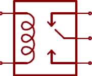
Connections
SD socket Circuit Diagram

| PLC | SD CARD |
| MOSI | MOSI |
| SCK | SCK |
| PIN 53 | CS |
| - | CD |
| MISO | DO |
| - | GND |
Software
Using the boards of Industrial Shields , there is a library that simplifies the uSD implementation called SD . It is the same as the Arduino library, with the only modification of using the pin 53 to select the ChipSelect of the uSD chip .
So, firstable it is necessary to include the SD.h library provided in our boards:
#include <SPI.h>
#include <SD.h>
Sd2Card card;
SdVolume volume;

///////////////////////////////////////////////////////////////////////////////////////////////
void setup() {
  Serial.begin(9600L);
  Serial.println("M-Duino PLUS test started");

// we'll use the initialization code from the utility libraries
// since we're just testing if the card is working!
  if (!card.init(SPI_HALF_SPEED, 53)) {
    Serial.println("initialization failed. Things to check:");
    Serial.println("* is a card inserted?");
    Serial.println("* is your wiring correct?");
    Serial.println("* did you change the chipSelect pin to match your shield or module?");
    return;
  } else {
    Serial.println("Wiring is correct and a card is present.");
  }

  // print the type of card
  Serial.print("\nCard type: ");
  switch (card.type()) {
    case SD_CARD_TYPE_SD1:
      Serial.println("SD1");
      break;
    case SD_CARD_TYPE_SD2:
      Serial.println("SD2");
      break;
    case SD_CARD_TYPE_SDHC:
      Serial.println("SDHC");
      break;
    default:
      Serial.println("Unknown");
  }

  // Now we will try to open the 'volume'/'partition' - it should be FAT16 or FAT32
  if (!volume.init(card)) {
    Serial.println("Could not find FAT16/FAT32 partition.\nMake sure you've formatted the card");
  } else {
    // print the type and size of the first FAT-type volume
    uint32_t volumesize;
    Serial.print("\nVolume type is FAT");
    Serial.println(volume.fatType(), DEC);
    Serial.println();

    volumesize = volume.blocksPerCluster();    // clusters are collections of blocks
    volumesize *= volume.clusterCount();       // we'll have a lot of clusters
    volumesize *= 512;                            // SD card blocks are always 512 bytes
    Serial.print("Volume size (bytes): ");
    Serial.println(volumesize);
    Serial.print("Volume size (Kbytes): ");
    volumesize /= 1024;
    Serial.println(volumesize);
    Serial.print("Volume size (Mbytes): ");
    volumesize /= 1024;
    Serial.println(volumesize);
  }
}

///////////////////////////////////////////////////////////////////////////////////////////////
void loop() {}
For more detailed information about SD class information check the SD library repository.