Detalles Técnicos
M-DUINO PLC Arduino Ethernet & GPRS 38AR I/Os Analog/Digital/Relay PLUS GPRS
VOLVER AL PRODUCTOInstalación Inicial
ARDUINO IDE
Arduino IDE es la plataforma original para programar placas Arduino. Esta aplicación multiplataforma está disponible en Windows, macOS y Linux y bajo la Licencia Pública General GNU.
Arduino IDE admite la estructuración de código C y C ++. Industrial Shields recomienda usar Arduino IDE para programar PLC basados en Arduino, pero cualquier software compatible con Arduino es compatible con los controladores Industrial Shields.
Aparte de eso, Industrial Shields brinda la posibilidad de seleccionar su PLC basado en Arduino en su IDE de Arduino y compilar sus bocetos para los diferentes PLC.
Descargue el IDE de Arduino 1.8.6:
FUENTE DE ALIMENTACIÓN
Todos los PLC basados en Arduino se pueden alimentar entre 12-24 V. Tanto la familia M-Duino como la familia Ardbox, tienen un consumo entre 700mA y 1500mA.
Por lo tanto, la fuente de alimentación recomendada es de 2 A o superior. Cualquier fuente de alimentación industrial será una buena opción para alimentarlos.
RECUERDE: Las unidades de salida están diseñadas para funcionar entre 12-24V. Simplemente alimentándolos con el USB, la unidad no podrá realizar sus funciones. USB es solo para programar los PLC, no para alimentarlos.
Si por alguna razón desea utilizar una fuente de alimentación inferior a 1,5 A, póngase en contacto con el soporte técnico de Industrial Shields para asegurarse de que su sistema completará sus funcionalidades sin ningún problema de energía.
A continuación se muestra un diagrama sencillo para ver cómo alimentar cualquier unidad Industrial Shields.

INTERRUPTOR
Nuestros tableros tienen la nomenclatura que se muestra a continuación:

La placa de comunicación (zona A) es compartida con toda la familia M-Duino, por esta razón puede ser que algunos interruptores no tengan funcionalidad o su posición no esté relacionada en su unidad. En la siguiente tabla se indica qué interruptores están relacionados con la unidad y su funcionalidad:
Zone A Interruptor Superior Izquierdo:

SCL / NC: SIEMPRE EN POSICIÓN APAGADA. En un MDuino 38AR Relés / Analógico / Digital PLUS este interruptor no está conectado.
SDA / NC: SIEMPRE EN POSICIÓN APAGADA. En un MDuino 38AR Relés / Analógico / Digital PLUS este interruptor no está conectado.
RX1/I1.1: Elegir entre RX1 o la entrada I1.1. Si este interruptor está en ON, habilita la entrada I1.1 y deshabilita el RX1. Si este interruptor está en OFF, habilita RX1 y deshabilita I1.1.
TX1/I1.0: Elegir entre TX1 o la entrada I1.0. Si este interruptor está en ON, habilita la entrada I1.0 y deshabilita el TX1. Si este interruptor está en OFF, habilita TX1 y deshabilita I1.0.
Pin 3/I0.6: Elegir entre el Pin 3 o la entrada I0.6. Si este interruptor está en ON, habilita la entrada I0.6 y deshabilita el Pin 3. Si este interruptor está en OFF, habilita el Pin 3 y deshabilita I0.6
.
GPRS RST /I0.5: SIEMPRE EN POSICIÓN APAGADA. GPRS RST e I0.5 son utilizados por el módulo Sim800L (el módulo modle / GSM).
D53(SD): SIEMPRE EN POSICIÓN APAGADA. En un MDuino 38AR Relés / Analógico / Digital PLUS este interruptor no está conectado.
FD RS-485 HD: Elegir entre (FD) o (HD). Si este interruptor está en ON, habilita la opción Half Duplex (HD) y deshabilita el (FD). Si este interruptor está en OFF, habilita Full Duplex (FD) y deshabilita (HD).
Zona A Izquierda Debajo del Interruptor :

NC: No conectado. Este interruptor no está conectado a nada, no importa si está en modo ENCENDIDO o APAGADO.
NC: No conectado. Este interruptor no está conectado a nada, no importa si está en modo ENCENDIDO o APAGADO.
RTC (SDA): Este interruptor permite que la comunicación se comunique con el RTC mediante I2C. Tener este interruptor en modo ON activa estecomunicación, mientras que si está en modo OFF deshabilita el I2C para alcanzar el RTC.
RTC (SCL): Este interruptor permite que la comunicación se comunique con el RTC mediante I2C. Tener este interruptor en modo ON activa estecomunicación, mientras que si está en modo OFF deshabilita el I2C para alcanzar el RTC.
Zona B Analógica:

INTERRUPTOR
ON
OFF
4
NC
NC
3
Q0.7
A0.7
2
Q0.6
A0.6
1
Q0.5
A0.5
Zona C Relay:

INTERRUPTOR
ON
OFF
4
NC
NC
3
Q1.2
A1.2
2
Q1.1
A1.1
1
Q1.0
A1.0
Entradas y Salidas
ENTRADAS ANALÓGICAS
La variación de voltaje entre –Vcc (o GND) y + Vcc, puede tomar cualquier valor. Una entrada analógica proporciona una medición codificada en forma de valor digital con un número de N bits. En las E / S digitales y analógicas hay autoaislamiento, por lo que es posible conectarlas a una fuente de alimentación diferente a la de 24 V.
Entradas: (10x) Analógico (0-10Vdc) / Digital (5-24Vdc) configurables por software.
Know more about Analog Inputs.
TYPICAL CONNECTION

ENTRADAS DIGITALES
Variación de tensión de –Vcc (o GND) a + Vcc, sin valores intermedios. Dos estados: 0 (-Vcc o GND) y 1 (+ Vcc). En las E / S digitales y analógicas hay autoaislamiento, por lo que es posible conectarlas a una fuente de alimentación diferente a la de 24 V.
Entradas digitales nos proporciona entrada PNP.
Entradas: (8x) Aisladas digitales (5-24Vdc), (3x) pueden funcionar como interrupción INT (7-24Vdc).
Know more about Digital Inputs.
TYPICAL CONNECTION
-Entrada digital aislada

- Entrada digital sin aislamiento

ENTRADAS DE INTERRUPCIÓN
Interrumpir la rutina del servicio. Mecanismo que permite asociar una función con la ocurrencia de un evento en particular. Cuando ocurre el evento, el procesador sale inmediatamente del flujo normal del programa y ejecuta la función ISR asociada ignorando cualquier otra tarea.
Entradas: (3x) Entradas de interrupción (7-24Vdc). "Puede funcionar como una entrada digital (24 V CC)"
| Interruptor | Pin Arduino Mega | Pin MDuino |
| INT1 | 3 | I0.6/INT1 |
| INT2 | 18 | I1.0/INT2 |
| INT3 | 19 | I1.1/INT3 |
- I0.6 también como Pin3, habilita las interrupciones encendiendo los interruptores número 4 del interruptor de comunicación descendente.
- I1.0 e I1.1 también como Tx1 y Rx1. Habilite las interrupciones activando los interruptores número 1 y 2 de los interruptores de comunicación.
TYPICAL CONNECTION

En este ejemplo activamos INT1 usando el pin I0_6 de la placa M-duino. Cuando hay un cambio
#define INTERRUPT I0_6 //other pins:I0_6, I2_6, I2_5, I1_6, I1_5 (M-Duino) I0_0, I0_3, I0_2, I0_1 (Ardbox)

volatile bool state = false;

void setup() {
  pinMode(INTERRUPT, INPUT_PULLUP);
  attachInterrupt(digitalPinToInterrupt(INTERRUPT), function_call_back, CHANGE);
}

void loop() {
  if (state == true){
    Serial.println("Interrupt activated");
    state = false;
  }
}

void function_call_back(){ //Change led state
  state = true;
}
SALIDAS ANALÓGICAS
La variación de voltaje entre –Vcc (o GND) y + Vcc, puede tomar cualquier valor. Una entrada analógica proporciona una medición codificada en forma de valor digital con un número de N bits. En las E / S digitales y analógicas hay autoaislamiento, por lo que es posible conectarlas a una fuente de alimentación diferente a la de 24 V.
Salidas: (6x) Analógica (0-10Vdc) configurable por interruptor.
Know more about Analog Outputs.
TYPICAL CONNECTION

SALIDAS DIGITALES
Variación de tensión de –Vcc (o GND) a + Vcc, sin valores intermedios. Dos estados: 0 (-Vcc o GND) y 1 (+ Vcc). En las E / S digitales y analógicas hay autoaislamiento, por lo que es posible conectarlas a una fuente de alimentación diferente a la de 24 V.
Salidas
(11x) Digital aislado (5-24Vdc) / PWM aislado
Know more about Digital Outputs.
TYPICAL CONNECTION

RELAYS
Un relé es un interruptor electromagnético controlado por una señal eléctrica. En las unidades de Industrial Shields estos dispositivos ya están integrados en sus placas y pueden ser accesibles directamente con la función digitalWrite (RX, HIGH). Los relés de Industrial Shields están normalmente abiertos y pueden manejar una corriente máxima de 5 A para un voltaje máximo de 250 Vca y 3 A para un voltaje máximo de CC de 30 V CC.
Salidas: (8x) Salidas de relé (220Vac - 5A).
Know more about Relay Output.
TYPICAL CONNECTION

SALIDAS PWM
Modulación de ancho de pulso. Active una salida digital por un tiempo y manténgala apagada por el resto. El voltaje de salida promedio, con el tiempo, será igual al valor analógico deseado. La frecuencia entre pulsos es la misma mientras se cambia el ancho del pulso. Atención: una salida PWM da un valor de Vcc durante un tiempo determinado. Entonces, durante un porcentaje de tiempo es 5v y el resto del tiempo es 0V. Si suministramos un dispositivo que necesita 3v, podemos dañarlo.
| M-Duino Pin | Ardino Mega Pin |
| Q0.7 | 6 |
| Q0.6 | 5 |
| Q0.5 | 4 |
| Q1.2 | 11 |
| Q1.1 | 10 |
| Q1.0 | 8 |
- Q0.5, Q0.6 y Q0.7 Salida digital / PWM también como salida analógica A0.5, A0.6 y A0.7.
Para usar los pines de configuración Digital / PWM (QX.X), debe encender los siguientes interruptores:


TYPICAL CONNECTION

Pulsos de módulo de biblioteca Tools40 library
El módulo de Pulsos proporciona funciones para iniciar y detener un tren de pulsos a la frecuencia deseada utilizando pines PWM. La función
startPulses(pin, frequency, precision)inicia el tren de pulsos a la frecuencia y precisión especificadas. La frecuencia predeterminada es 1 kHz y la precisión predeterminada es 3.La función stopPulses(Pin) detiene el tren de pulsos.pinMode(3, OUTPUT);
startPulses(3, 2000, 3);
stopPulses(3);
IMPORTANTE: It is not possible to have different frequencies between the same TIMER Pin’s. Some outputs share the same timer, so they work at the same frequency.
¡¡¡PRECAUCIÓN!!! Cuando se utilizan los pines TIMER0, todas las funciones de tiempo cambian su funcionalidad como delay (), millis (), micros (), delayMicroseconds () y otras.
A continuación se muestra la precisión recomendada entre diferentes frecuencias:
| Precision | Frequency Range (Hz) |
| 1 | 30 - 150 |
| 2 | 150 - 500 |
| 3 | 500 - 4k |
| 4 | 4k - 32k |
| 5 | 32k - 4M |
Para tener una alta precisión en la frecuencia deseada, se recomienda utilizar la precisión más cercana a los valores de la tabla anterior.
SALIDAS DE INTERRUPCIÓN
Interrumpir la rutina del servicio. Mecanismo que permite asociar una función con la ocurrencia de un evento en particular. Cuando ocurre el evento, el procesador sale inmediatamente del flujo normal del programa y ejecuta la función ISR asociada ignorando cualquier otra tarea.
| Interruptor | Pin Arduino Mega | Pin MDuino |
| INT1 | 3 | I0.6/INT1 |
| INT2 | 18 | I1.0/INT2 |
| INT3 | 19 | I1.1/INT3 |
- I0.6 / INT1 también como Pin3 habilita las interrupciones encendiendo el interruptor número 4 del interruptor de comunicación descendente.
- I1.0 / INT3 e I1.1 / INT2 también como Tx1 y Rx1. Habilite las interrupciones activando los interruptores número 1 y 2 de los interruptores de comunicación.
Code example
In this example we activate INT1 using pin I0_6 from M-duino board. When there’s a change
#define INTERRUPT I0_6 //other pins: I2_6, I2_5, I1_6, I1_5 (M-Duino) I0_0, I0_3, I0_2,  (Ardbox)

volatile bool state = false;

void setup() {
  pinMode(INTERRUPT, INPUT_PULLUP);
  attachInterrupt(digitalPinToInterrupt(INTERRUPT), function_call_back, CHANGE);
}

void loop() {
  if (state == true){
    Serial.println("Interrupt activated");
    state = false;
  }
}

void function_call_back(){ //Change led state
  state = true;
}
Communications
Ethernet
Ethernet is the technology that is most commonly used in wired local area networks ( LANs ).
A LAN is a network of computers and other electronic devices that covers a small area such as a room, office, or building. It is used in contrast to a wide area network (WAN) , which spans much larger geographical areas. Ethernet is a network protocol that controls how data is transmitted over a LAN. Technically it is referred to as the IEEE 802.3 protocol. The protocol has evolved and improved over time to transfer data at the speed of a gigabit per second.
Our M-Duino family incorporate the integrated W5500 IC.
WX5500 is a Hardwired TCP/IP embedded Ethernet controller that provides easier Internet connection to embedded systems. This chip enables users to have Internet connectivity in their applications by using the single chip in which TCP/IP stack, 10/100 Ethernet MAC and PHY are embedded. The W5500 chip embeds the 32Kb internal memory buffer for the Ethernet packet processing. With this chip users can implement the Ethernet application by adding the simple socket program. SPI is provided for easy integration with the external microcontroller.
Hardware
Hardware configuration
*IMPORTANT:
Make sure that your Ethernet PLC is powered (12-24Vdc). Just with USB is insufficient power to power up the
Ethernet communication.
Switch configuration
For the Ethernet communication protocol there isn’t
any switch
that
affects
it. So it does not matter the configuration of the
switches to implement Ethernet communication.
Used pins
For Ethernet communication protocol, the defined
Arduino Mega
pin is
pin 10
, which is connected and already internally
assembled to the
WX5500
Ethernet controller. W5500 IC communicates to the Mega board via
SPI bus
already assembled too.
You can
access easily to
Ethernet port
in our Ethernet PLCs, it is located at the top of the communications layer.
Ethernet hardware configuration must be plug and play.
Software
*IMPORTANT: Make sure to download the Arduino based PLC boards for Arduino IDE.
Software Configuration:
Once the hardware configuration is done, it is possible to proceed with the software configuration and also its usage. Firstable it is necessary to include
the Ethernet2.h library provided by Industrial Shields (has the same functionallity as Ethernet.h and also
the same usage).
#include <Ethernet2.h> * Remember that for the V7 version or earlier versions you must use the <Ethernet.h> library.Ethernet2 Library - functions.
* Ethernet2.h library has the same functions as Ethernet.h.
For Ethernet communication there is 3 protocols available:
- Ethernet with HTTP. to know more.
- Ethernet with MQTT, to know more.
- Ethernet with Modbus TCP/IP.
- Master, know more.
- Slave, know more.
Sample example Codes:
Echo TCP Server:
Once the server is running, any client can connect to the server. On this example it is used an M-Duino to generate the server. The
example of TCP client showed before could be one of the clients.
Next it is showed the Arduino IDE code:
// use Ethernet.h if you have a M-Duino V7 version
#include <Ethernet2.h>
// mac address for M-Duino
byte mac[] = { 0xBE, 0xAD, 0xBE, 0xEF, 0xFE, 0xED };
// Ip address for M-Duino
byte ip[] = { 192, 168, 1, 100 };
int tcp_port = 5566;
EthernetServer server = EthernetServer(5566);
void setup()
{
  // initialize the ethernet device
  Ethernet.begin(mac, ip);
  // start server for listenign for clients
  server.begin();
}
void loop()
{
  // if an incoming client connects, there will be bytes available to read:
  EthernetClient client = server.available();
  if (client.available()) {
    // read bytes from the incoming client and write them back
    // to the same client connected to the server
    client.write(client.read());
  }
}
Once the server is running, M-Duino can connect to the server. On this example it is used an M-Duino to connect with the Node.js
server called server.js, the same as used on previous example link.
To configure the M-Duino, this post just follows the TCP example from Arduino web site with a few changes. To be able to connect to the server we must know the TCP
server IP and the port where this server is listening.
Next it is showed the Arduino code:
#include <Ethernet2.h>
#include <SPI.h>
byte mac[] = { 0xBE, 0xAD, 0xBE, 0xEF, 0xFE, 0xED };
byte ip[] = { 192, 168, 1, 100 };
byte server[] = { 192, 168, 1, 105 }; // Touchberry Pi Server
int tcp_port = 5566;
EthernetClient client;
void setup()
{
  Ethernet.begin(mac, ip);
  Serial.begin(9600);
  delay(1000);
  Serial.println("Connecting...");
  if (client.connect(server, tcp_port)) { // Connection to server.js
    Serial.println("Connected to server.js");
    client.println();
  } else {
    Serial.println("connection failed");
  }
}
void loop()
{
  if (client.available()) {
    if(Serial.available()){
      char s = Serial.read();
      client.write(s); // Send what is reed on serial monitor
      char c = client.read();
      Serial.print(c); // Print on serial monitor the data from server
    }
  }
  if (!client.connected()) {
    Serial.println();
    Serial.println("disconnecting.");
    client.stop();
    for(;;) ;
  }
}
RS-485
RS-485 also known as TIA-485(-A), EIA-485, is a standard defining the electrical characteristics of drivers and receivers for use in serial communications systems. Electrical signaling is balanced, and multipoint systems are supported.
Our Arduino Based PLCs incorporate the integrated circuit MAX485.
MAX485
is a low-power and slew-rate-limited transceiver used for
RS-485 communication
. It works at a single +5V power supply and the rated current is 300 μA. Adopting half-duplex communication to implement the function of converting TTL level into
RS-485 level, it can achieve a maximum transmission rate of 2.5Mbps. MAX485 transceiver draws supply current of between 120μA and 500μA under the unloaded or fully loaded conditions when the driver is disabled.
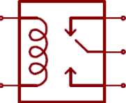
There is internally installed a
half duplex MAX485
and
MAX485 transmitter
. If you are working on
full duplex
you will use the
MAX485 half duplex to receive data and MAX485 transmitter to send the data.
Hardware
Switch configuration
For the RS-485 communication protocol there is only one switch that affects in this communication. The RS-485 protocol will be
always enabled, the only switch that affects is the one called "FD rs-485 HD". This switch makes the choosing between RS-485 HalfDuplex or RS-485 Full Duplex.

| "FD RS-485 HD" (ON Position) | "FD RS-485 HD" (OFF Position) |
| Half Duplex | Full Duplex |
}
Used pins
For RS-485 communication protocol the defined Arduino Mega pins are showed in the chart below:
| MDuino 21+ pinout | Arduino Mega pinout |
| DI (Tx) | 14 (Tx Serial3) |
| RO(Rx) | 15 (Rx Serial3) |
| RE (Inverted logic) | 11 |
| DE | 46 |
Software
IMPORTANT:
Make sure to download the
Arduino based PLC boards
for Arduino IDE.
Software Configuration:
Once the hardware configuration is done, it's possible to proceed with the software configuration and also its usage. Firstable it's
necessary to include the RS485.h library provided in our boards.
#include <RS485.h>
To check if the RS-485 port is working it is easy to use the serial monitor from the Arduino IDE using the right sentence inside the
setup() function:
Serial.begin(9600);
Then don’t forget to implement the proper initialization of your communication on the setup() function.
RS485.begin(38400);
NOTE:
Check the velocity of transmission between the PLC and the Laptop and from the PLC to the device connected by RS-485.
Example Codes
Basic RS-485 write example (send):
// Include Industrial Shields libraries
#include <RS485.h>

//// IMPORTANT: check switches configuration

////////////////////////////////////////////////////////////////////////////////////////////////////
void setup() {
  // Begin serial port
  Serial.begin(9600);

  // Begin RS485 port
  RS485.begin(38400);
}

////////////////////////////////////////////////////////////////////////////////////////////////////
void loop() {
  // Wait bytes in the serial port
  if (Serial.available()) {
    byte tx = Serial.read();

    // Echo the byte to the serial port again
    Serial.write(tx);

    // And send it to the RS-485 port
    RS485.write(tx);
  }
}
Basic RS-485 read example (receive):
// Include Industrial Shields libraries
#include <RS485.h>

//// IMPORTANT: check switches configuration

////////////////////////////////////////////////////////////////////////////////////////////////////
void setup() {
  // Begin serial port
  Serial.begin(9600);

  // Begin RS485 port
  RS485.begin(38400);
}
////////////////////////////////////////////////////////////////////////////////////////////////////
void loop() {
  // Print received byte when available
  if (RS485.available()) {
    byte rx = RS485.read();

    // Hexadecimal representation
    Serial.print("HEX: ");
    Serial.print(rx, HEX);

    // Decimal representation
    Serial.print(", DEC: ");
    Serial.println(rx, DEC);
  }
}
Basic RS-485 full-duplex example:
* Remember that to test the full duplex with your Ethernet PLC you must connect the A, B (receivers) to the Y, X(transmitters).
// Include Industrial Shields libraries
#include <RS485.h>
//// IMPORTANT: check switches configuration
//// IMPORTANT: Full duplex mode is only available when device supports it
////////////////////////////////////////////////////////////////////////////////////////////////////
void setup() {
  // Begin serial port
  Serial.begin(9600);
  // Begin RS485 port
  RS485.begin(38400, FULLDUPLEX);
}

////////////////////////////////////////////////////////////////////////////////////////////////////
void loop() {
  // Wait bytes from the RS-485
  if (RS485.available()) {
    byte tx = RS485.read();
    // In full-duplex mode it is possible to send and receive data
    // at the same time in a secure way
    RS485.write(tx);
    // Echo the byte to the serial port
    Serial.write(tx);
  }
}
Important: Using RS-485 we can also implement Modbus RTU see more.
Serial TTL
Communication Interface between two devices with a low level voltage. A Serial port sends data by a bit sequence.
Two signals: Tx (Transmit Data) and Rx (Receive Data).
M-Duino has two TTL ports, RX0/TX0, RX1/TX1. TTL0 is accessed with the function Serial (pins 0 and 1 of the Arduino Mega). TTL1 is accessed with the function Serial1 (pins 18 and 19 of the Arduino Mega).
Hardware
IMPORTANT: Make sure that your Ethernet PLC is powered (12-24Vdc).
Switch configuration
To achieve Serial TTL communication there isn't any switch that affects it, it is always enabled. So it does not matter the configuration of the switches to implement Serial TTL
communication.
Used pins
| MDuino Ethernet & GPRS PLC Pinout | Arduino Mega Pinout |
| Tx 0 | 0 |
| Rx 0 | 1 |
| Tx 1 | 18 |
| Rx 1 | 19 |
Software
IMPORTANT: Make sure to download the Arduino based PLC boards for Arduino IDE.
Software Configuration
Once the hardware configuration is done, it's possible to proceed with the software configuration and also its usage. Firstable it's necessary to include the RS232.h library provided in
our boards. Then don’t forget to implement the proper initialization of your communication on the setup() function:
Serial.begin(9600);
Basic Serial TTL write example
Reads an analog input on Tx0 (pin 0), prints the result to the serial monitor.
Graphical representation is available using serial plotter (Tools > Serial Plotter menu) on Arduino IDE serial monitor.
// the setup routine runs once when you press reset:
void setup() {
  pinMode(I0_2, INPUT);
  // initialize serial communication at 9600 bits per second:
  Serial.begin(9600);
}
// the loop routine runs over and over again forever:
void loop() {
  // read the input on analog pin 0:
  int sensorValue = analogRead(I0_2);
  // print out the value you read:
  Serial.println(sensorValue);
  delay(1);        // delay in between reads for stability
}
I2C
I2C is a synchronous protocol. Only uses 2 cables, one for the clock (SCL) and one for the data (SDA). This means that the master and the slave send data through the same
cable, which is controlled by the master, who creates the clock signal. I2C does not use slave selection, but addressing.
I2C is a serial communications bus. The speed is 100 kbit/s in standard mode, but also allows speeds of 3.4 Mbit/s. It is a bus very used in the industry, mainly to
communicate microcontrollers and their peripherals in integrated systems and generalizing more to communicate integrated circuits among themselves that normally reside
in a same printed circuit.
Hardware
IMPORTANT: Make sure that your Ethernet PLC is powered (12-24Vdc).
Switch configuration
To achieve I2C communication there isn't any switch that affects it, it is always enabled. So it does not matter the configuration of the switches to implement I2C communication.
Used pins
| MDuino Ethernet PLC Pinout | Arduino Mega Pinout |
| SDA | 20 |
| SCL | 21 |
Software
IMPORTANT: Make sure to download the Arduino based PLC boards for Arduino IDE.
Example of Master Writer.
#include <Wire.h>

void setup() {
  Wire.begin(); // join i2c bus (address optional for master)
}

byte x = 0;

void loop() {
  Wire.beginTransmission(8); // transmit to device #8
  Wire.write("x is ");        // sends five bytes
  Wire.write(x);              // sends one byte
  Wire.endTransmission();    // stop transmitting

  x++;
  delay(500);
}
#include <Wire.h>

void setup() {
  Wire.begin(8);                // join i2c bus with address #8
  Wire.onReceive(receiveEvent); // register event
  Serial.begin(9600);           // start serial for output
}

void loop() {
  delay(100);
}

// function that executes whenever data is received from master
// this function is registered as an event, see setup()
void receiveEvent(int howMany) {
  while (1 < Wire.available()) { // loop through all but the last
    char c = Wire.read(); // receive byte as a character
    Serial.print(c);         // print the character
  }
  int x = Wire.read();    // receive byte as an integer
  Serial.println(x);         // print the integer
}
Know more about I2C.
SPI
These pins can only work as a 5V pins if the Ethernet protocol is not going to be used. As the Ethernet protocol uses the SPI to communicate with the Arduino board, both
behaviours cannot happen at the same time as the Ethernet would not work.
These pins are not stablished with a pull-up or a pull-down configuration. The state of thesepins is unknown. If these pins must be used, they require a pull-up or a pull-down
configuration. The Arduino board allows the pins to be set in a pull-up configuration. If not itmust be stablished an external pull-up or pull-down circuit in order to correctly
work with these pins.
Hardware
IMPORTANT: Make sure that your Ethernet PLC is powered (12-24Vdc).
Switch configuration
To achieve SPI communication there isn't any switch that affects it, it is always enabled. So it does not matter the configuration of the switches to implement SPI communication.
Used pins
For Serial communication protocol the defined Arduino Mega pins are showed in the chart below. For SPI bus MISO, MOSI and CLOCK pins are
common to all the connected devices to the M-Duino, conversely, each of the connected devices will have a single and dedicated SS pin.
| Function | M-Duino connection | Arduino Mega Pinout |
| MISO | SO | 50 |
| MOSI | SI | 51 |
| CLOCK | SCK | 52 |
| RST | Reset | Reset |
IMPORTANT: Make sure to download the Arduino based PLC boards for Arduino IDE.
// inslude the SPI library:
#include <SPI.h>


// set pin 10 as the slave select for the digital pot:
const int slaveSelectPin = 10;

void setup() {
  // set the slaveSelectPin as an output:
  pinMode(slaveSelectPin, OUTPUT);
  // initialize SPI:
  SPI.begin();
}

void loop() {
  // go through the six channels of the digital pot:
  for (int channel = 0; channel < 6; channel++) {
    // change the resistance on this channel from min to max:
    for (int level = 0; level < 255; level++) {
      digitalPotWrite(channel, level);
      delay(10);
    }
    // wait a second at the top:
    delay(100);
    // change the resistance on this channel from max to min:
    for (int level = 0; level < 255; level++) {
      digitalPotWrite(channel, 255 - level);
      delay(10);
    }
  }

}

void digitalPotWrite(int address, int value) {
  // take the SS pin low to select the chip:
  digitalWrite(slaveSelectPin, LOW);
  //  send in the address and value via SPI:
  SPI.transfer(address);
  SPI.transfer(value);
  // take the SS pin high to de-select the chip:
  digitalWrite(slaveSelectPin, HIGH);
}
Know more about SPI.Special Functions
RTC
El término reloj en tiempo real se utiliza para evitar confusiones con los relojes de hardware ordinarios, que son solo señales que gobiernan la electrónica digital y no cuentan el tiempo en unidades humanas. RTC no debe confundirse con la computación en tiempo real, que comparte el acrónimo pero no se relaciona directamente con la hora del día.
Aunque el control del tiempo se puede hacer sin un RTC, usar uno tiene beneficios:
- Bajo consumo de energía (importante cuando se ejecuta con energía alternativa
- Libera el sistema principal para tareas de tiempo crítico
- A veces más preciso que otros métodos
Configuración de hardware
IMPORTANTE: Asegúrese de que su PLC Ethernet esté alimentado (12-24Vdc) .
Configuración del interruptor
RTC trabaja con el protocolo de comunicación I2C, por lo que se requiere tener habilitado el protocolo I2C.
Se deben configurar 4 interruptores para habilitar las funciones de RTC y la comunicación I2C:
| INTERRUPTOR | ON | OFF |
| 4 | NC | NC |
| 3 | NC |
NC |
| 2 | RTC | - |
| 1 | RTC | - |
RTC SCL y RTC SDA debe configurarse en modo ON para habilitar los cables I2C al RTC. Si están en modo APAGADO, el Arduino no se comunicará con el RTC.
Configuración de software
Una vez que se realiza la configuración del hardware, es posible continuar con la configuración del software y también su uso. Primero es necesario incluir la librería RTC.h proporcionada en nuestras placas (RTC.h incluye inicialización I2C.h, por lo que no será necesario inicializar la librería I2C.h):
#include <RTC.h>
Para verificar si el puerto RS-485 está funcionando, es fácil usar el monitor serial del IDE de Arduino usando la oración correcta dentro de la función setup ():
#Serial.begin(9600L)
Example Code
Prueba básica de RTC
// RTC library example
// by Industrial Shields
#include <RTC.h>
////////////////////////////////////////////////////////////////////////////////////////////////////
void setup() {
  Serial.begin(9600L);
}
///////////////////////////////////////////////////////////////////////////////////////////////////
void loop() {
  if (!RTC.read()) {
    Serial.println("Read date error: is time set?");
    }
     else {
    Serial.print("Time: ");
    Serial.print(RTC.getYear());
    Serial.print("-");
    Serial.print(RTC.getMonth());
    Serial.print("-");
    Serial.print(RTC.getMonthDay());
    Serial.print(" ");
    Serial.print(RTC.getHour());
    Serial.print(":");
    Serial.print(RTC.getMinute());
    Serial.print(":");
    Serial.print(RTC.getSecond());
    Serial.print(" (");
    Serial.print(RTC.getTime());
    Serial.println(")");
  }
  delay(1000);
}
SD
Secure Digital (SD) es un formato de tarjeta de memoria no volátil desarrollado por SD Card Association (SDA) para su uso en dispositivos portátiles.
Las familias más nuevas de tarjetas SD mejoran la velocidad de la tarjeta al aumentar la velocidad del bus (la frecuencia de la señal del reloj que envía información estroboscópica dentro y fuera de la tarjeta).
Cualquiera que sea la tarifa del bus, la tarjeta puede indicarle al host que está "ocupado" hasta que se complete una operación de lectura o escritura. El cumplimiento de una clasificación de velocidad más alta es una garantía de que la tarjeta limita el uso de la indicación "ocupado". Tamaño: 15 x 11 x 1 mm

General Features
La capacidad máxima es de 4 GB. Si se utiliza una capacidad superior, funcionará correctamente, pero solo funcionarán los primeros 4 GB. Arquitecturas de
sistema de archivos permitidas: FAT32 y FAT16.
La micro SD utiliza la comunicación SPI para interactuar con Arduino Mega. El protocolo SPI siempre está habilitado, ya que no hay conmutadores que lo configuren.
Sin embargo, hay un interruptor que debe colocarse en modo ON para comunicarse con el uSD:
D53 (SD): Si este interruptor está APAGADO, habilita la selección de chip del zócalo microSD y deshabilita Q2.0. Si este interruptor está en ON, habilita la salida Q2.0, por lo que si el interruptor está en modo ON, no se puede usar la microSD.
 }
}
Utilizando las placas de Industrial Shields, existe una biblioteca que simplifica la implementación de uSD
llamado SD. Es lo mismo que la biblioteca Arduino, con la única modificación de usar el pin 53 para seleccionar el Chip Select del chip uSD.
Conexiones
Diagrama de circuito de la toma SD

| PLC | SD CARD |
| MOSI | MOSI |
| SCK | SCK |
| PIN 53 | CS |
| - | CD |
| MISO | DO |
| - | GND |
Software
Utilizando las placas de Industrial Shields, existe una biblioteca que simplifica la implementación de uSD llamada SD. Es lo mismo que la biblioteca Arduino, con la única modificación de usar el pin 53 para seleccionar el ChipSelect del chip uSD.
Entonces, primero es necesario incluir la biblioteca SD.h proporcionada en nuestras placas:
#include <SPI.h>
#include <SD.h>
Sd2Card card;
SdVolume volume;

///////////////////////////////////////////////////////////////////////////////////////////////
void setup() {
  Serial.begin(9600L);
  Serial.println("M-Duino PLUS test started");

// we'll use the initialization code from the utility libraries
// since we're just testing if the card is working!
  if (!card.init(SPI_HALF_SPEED, 53)) {
    Serial.println("initialization failed. Things to check:");
    Serial.println("* is a card inserted?");
    Serial.println("* is your wiring correct?");
    Serial.println("* did you change the chipSelect pin to match your shield or module?");
    return;
  } else {
    Serial.println("Wiring is correct and a card is present.");
  }

  // print the type of card
  Serial.print("\nCard type: ");
  switch (card.type()) {
    case SD_CARD_TYPE_SD1:
      Serial.println("SD1");
      break;
    case SD_CARD_TYPE_SD2:
      Serial.println("SD2");
      break;
    case SD_CARD_TYPE_SDHC:
      Serial.println("SDHC");
      break;
    default:
      Serial.println("Unknown");
  }

  // Now we will try to open the 'volume'/'partition' - it should be FAT16 or FAT32
  if (!volume.init(card)) {
    Serial.println("Could not find FAT16/FAT32 partition.\nMake sure you've formatted the card");
  } else {
    // print the type and size of the first FAT-type volume
    uint32_t volumesize;
    Serial.print("\nVolume type is FAT");
    Serial.println(volume.fatType(), DEC);
    Serial.println();

    volumesize = volume.blocksPerCluster();    // clusters are collections of blocks
    volumesize *= volume.clusterCount();       // we'll have a lot of clusters
    volumesize *= 512;                            // SD card blocks are always 512 bytes
    Serial.print("Volume size (bytes): ");
    Serial.println(volumesize);
    Serial.print("Volume size (Kbytes): ");
    volumesize /= 1024;
    Serial.println(volumesize);
    Serial.print("Volume size (Mbytes): ");
    volumesize /= 1024;
    Serial.println(volumesize);
  }
}

///////////////////////////////////////////////////////////////////////////////////////////////
void loop() {}
Para obtener información más detallada sobre la clase SD, consulte la SD library repository.