Programando Arduino en Ambientes Industriales
Curso de 10 Capítulos de Contenido General [IS.AC001.GC]
#0 HANDY MATERIAL TO DEVELOP AN INDUSTRIAL PROJECT USING ARDUINO
Imagino que ya sabrás qué es Arduino por lo que en este curso nos centraremos en cómo utilizar en entornos industriales placas Arduino y los PLCs basados en Arduino para realizar proyectos un 30% más rápido.
Utilizando diferentes herramientas simples conseguirás sacar un alto rendimiento a la programación de Arduino y a la creación de proyectos con Arduino. El tiempo en un proyecto industrial es dinero por lo que te vamos a mostrar cómo ahorrar un 30% de tu tiempo.
- Verifica y evalúa las diferentes variables y señales conectadas a tu PLC con una interfaz gráfica.
- Utiliza ejemplos ya creados para no tener que empezar desde cero. (Si, ejemplos, no hace falta que el código inicial sea tuyo. Existen muchos ejemplos válidos para desarrollar tu proyecto)
- Utiliza librerías para tus funciones estándar.
(Recuerda: Para nosotros un PLC funciona cómo una placa Arduino. Nuestros PLCs utilizan placas Arduino originales por lo que puedes probar este curso utilizando placas Arduino originales).
Prepara este material en tu ordenador para empezar el capítulo 1.
Utilizando una una simple plataforma gráfica se puede visualizar el estado del PLC cómodamente y de forma amigable. Esta también la puedes utilizar como SCADA en tu proyecto y lo podrás integrar en tus proyectos como interfaz Hombre-Maquina. Simple, fácil y sin coste. Te recomendamos utilizar una plataforma Open Source llamada PROCESSING. (El Arduino IDE se basa en esta plataforma por lo que te resultará muy familiar).
Utiliza el Arduino IDE para programar tu PLC. Repasar los diferentes ejemplos del Arduino IDE ayuda para no tener que empezar desde cero tu proyecto. Con el Arduino IDE sólo tienes que seleccionar la placa Arduino que utilizas y el puerto USB en el que está conectado el equipo.
To configure the different inputs and outputs from the Industrial Shields PLC is easy.
You can also use the library from GitHub and forget the pinout checking. See how to upload the library from our blog.
Please, answer this Survey will help us to improve the course.
Conecta una placa Arduino al portátil
Es necesario saber 2 cosas esenciales:
Mediante el uso de Processing es posible disponer de una Interfaz Gráfica realizada de forma fácil y sencilla que nos permita monitorizar e interactuar con el PLC y controlar toda su instalación.
Arduino IDE nos permite utilizar librerías donde llamar a nuestros algoritmos estándar y desarrollar un programa estructurado. Te animamos a que veas la versión actual de la Librería original de Industrial Shields desde GitHub, para que puedas ver cómo están estructuradas las carpetas. En los siguientes capítulos veremos cómo desarrollar una Librería y cómo llamarla utilizando Arduino IDE.
(Recuerda: los PLCs de Industrial Shields funcionan como placas Arduino originales. Nuestros PLCs tienen placas Arduino originales montadas en su interior. Entonces, puedes practicar el curso usando una placa Arduino Original).
Enlaces útiles
Material para practicar
- Arduino Leonardo o Arduino Mega (También puedes usar un Arduino UNO).
(The devices used with the Arduino Mega and Arduino Leonardo assembled inside have been: From the Ethernet PLCs; the M-duino21. From the 20I/Os PLC; The
Por favor, contesta esta
Encuesta
y ayúdanos a mejorar el Curso.
#2 INPUTS
Tienes que saber 2 cosas muy básicas:
You can do the course practices using an original Arduino board. In fact, our PLCs have an original Arduino board assembled inside, So, it is not necessary to do practices using our devices if you don’t want. You can use an Arduino Leonardo board, which is the board used in our 20I/Os PLCs (they are called:
Alerta conexionado:
Es importante tener en cuenta que cuando conectes una entrada a una placa Arduino esta no puede ser superior a 5Vcc. Por lo que si utilizas un sensor industrial que trabaje a 24Vdc no lo podrás conectar directamente a esta placa. En cualquier caso con los diferentes PLCs puedes conectar sensores industriales hasta 24Vcc.
(Recuerda: Para nosotros un PLC funciona cómo una placa Arduino. Nuestros PLCs utilizan placas Arduino originales por lo que puedes probar este curso utilizando placas Arduino originales).
Si quieres utilizar sensores analógicos, la placa Arduino trabaja de 0 a 5Vcc. No puedes conectar tensiones superiores. Por otro lado, en la industria nos encontramos sensores analógicos que ofrecen una señal del tipo 4-20mA o señales de 0-10Vcc. La conversión de una señal analógica que funciona con intensidad es muy sencillo transformarlo a Voltaje ya que, por la LEY de OHM puedesconvertir 4-20mA a 0-10Vcc.
Links de interés:
Material para poder practicar:
- Arduino Leonardo o Arduino Mega (También puedes utilizar una placa Arduino UNO si la tienes).
(The devices used with the Arduino Mega and Arduino Leonardo assembled inside have been: From the Ethernet PLCs; the M-duino21. From the 20I/Os PLC; The
Please, answer this Survey and help us to improve the Course.
#3 OUTPUTS
Tienes que saber 2 cosas muy básicas:
You can do the course practices using an original Arduino board. In fact, our PLCs have an original Arduino board assembled inside, So, it is not necessary to do practices using our devices if you don’t want. You can use an Arduino Leonardo board, which is the board used in our 20I/Os PLCs (they are called:
Alerta conexionado:
Las salidas de los PLCs ofrecen voltaje por lo que es importante que tengas en cuenta la polaridad de los diferentes elementos que conectes a estas. El voltaje de las salidas que no estén Opto-aisladas será el mismo que el voltaje de alimentación del equipo. Lo que será 12Vcc o 24Vcc en función de la tensión de alimentación del PLC. Para las salidas Opto-aisladas se puede conectar el voltaje de 5 a 24Vcc. Es importante conectar también el común a estas salidas, según se indica en el esquema del PLC. Para gobernar una salida digital utilizaras la sentencia DigitalWrite().
(Recuerda: Para nosotros un PLC funciona cómo una placa Arduino. Nuestros PLCs utilizan placas Arduino originales por lo que puedes probar este curso utilizando placas Arduino originales).
Las salidas analógicas se programan exactamente igual que una salida PWM. En las placas Arduino las señales PWM trabajaran a 5Vcc. Para los PLCs el voltaje dependera del Vcc conectado al equipo. En caso de conectar las salidas Analógicas estas siempre serán de 0-10Vcc. La resolución de estas señales es de 8bits por lo que puedes variar el valor de la señal de 0 a 255 utilizando la sentencia AnalogWrite().
- Links de interés:
Material para poder practicar:
- Arduino Leonardo o Arduino Mega (También puedes utilizar una placa Arduino UNO si la tienes).
(The devices used with the Arduino Mega and Arduino
Please, answer this Survey and help us to improve the Course.
Tienes que saber algunas cosas muy básicas:
You can practice with an Arduino board. In the different PLCs we use original Arduino boards, for this
A menudo, cuando se leen entradas en un PLC se almacena su estado en una variable. Esta variable se puede utilizar para enviar su estado a través de algún sistema de comunicación (RS485, RS232, Ethernet, Serial TTL, etc.) o también para realizar una serie de funciones tales como filtros, trabajar por flancos, contadores, etc. Para activar una salida también es común utilizar una seria de variables que serán las encargadas de definir el estado de la salida en cuestión.
Trabajo para el alumno
Te vamos a hacer trabajar. Ahora deberías saber como leer una entrada digital y una entrada analógica. También deberías saber activar una salida digital y una salida analógica. (Recuerda que las salidas analógicas se programan igual que las salidas PWM si bien unas te dan una señal por pulsos y la otra te ofrece una señal analógica 0-10 Vdc en función al valor que según las salidas de 8 bits oscila entre 0-255).
(Recuerda: Para nosotros un PLC funciona cómo una placa Arduino. Nuestros PLCs utilizan placas Arduino originales por lo que puedes probar este curso utilizando placas Arduino originales).
Enlaces útiles
Material para practicar
-
Arduino Leonardo o Arduino Mega (También puedes utilizar la placa Arduino UNO).
(The equipment used with the Arduino Mega and Arduino Leonardo boards inside it were: the Ethernet PLC family, the M-duino21 and the basic 20 I / Os PLCs, the
Por favor, contesta esta Encuesta y ayúdanos a mejorar el Curso.
#5 VARIABLES I
Al leer este capitulo tienes que tener en cuenta una serie de puntos:
You can practice with an Arduino board. In the different PLCs we use original Arduino boards, for this
En este capitulo te contamos unas nociones básicas de los tipos de variables que tratamos en un programa. Esto es importante ya que utilizar la variable del tipo adecuado en un proyecto es clave para evitar posibles problemas a la hora de operar con estas. También te permite optimizar bien el código cosa que agradecerás cuando vayas a utilizar diferentes sistemas de comunicación con los equipos (RS485, RS232, Ethernet, Serial TTL, etc) Todo lo que veremos en este capitulo te sirve tanto para la programación en General, no solo para la programación de Arduino pero es muy importante conocer y saber que existe diferencias entre los diferentes tipos de Variables. Y también ciertas similitudes entre una u otra por lo que tampoco será tienes que sentirte agobiado al ver este temario. Con los diferentes capítulos verás y asimilaras el uso de un tipo y otro.
Repaso del temario:
En este capitulo te vamos, a parte de ver el vídeo te recomendamos que te leas los diferentes tipos de variables que tratamos.
En el vídeo te mostramos de dónde puedes ver esta información por lo que de forma muy rápida puedes repasar el temario de este capitulo. El objetivo es que puedas identificar los diferentes tipos de variables tratados así como tener una idea de cuando utilizar un tipo u otro.
(Remember: For
Links de interés:
Material para poder practicar:
- Arduino Leonardo o Arduino Mega (También puedes utilizar una placa Arduino UNO si la tienes).
(The equipment used with the Arduino Mega and Arduino Leonardo boards inside it were: the Ethernet PLC family, the M-duino21 and the basic 20 I / Os PLCs, the
Please, answer this Survey and help us to improve the Course.
#6 VARIABLES II
Al leer este capitulo tienes que tener en cuenta una serie de puntos:
You can practice with an Arduino board. In the different PLCs we use original Arduino boards, for this
In this chapter we continue with the types of variables that we treat in a program, where we left it in the previous chapter. This is important since using the variable of the appropriate type in a project is key to avoid possible problems when operating with these. It also allows you to optimize well the code thing that you will appreciate when you go to use different systems of communication with the equipment (RS485, RS232, Ethernet, Serial TTL, etc) Everything what we will see in this chapter serves you so much for the programming in General, not only for Arduino programming but it is very important to know and know that there are differences between the different types of Variables. And also certain similarities between one or the other so you will not have to feel overwhelmed to see this agenda. With the different chapters you will see and assimilate the use of one type and another.
Variables:
It is important to be clear about how different truths are declared and what options we have in each of them. In the final part of the
In the
(Remember: For
Links de interés:
Material para poder practicar:
- Arduino Leonardo o Arduino Mega (También puedes utilizar una placa Arduino UNO si la tienes).
(The equipment used with the Arduino Mega and Arduino Leonardo boards inside it were: the Ethernet PLC family, the M-duino21 and the basic 20 I / Os PLCs, the
Please, answer this Survey and help us to improve the Course.
#7 COMMUNICATIONS
Al leer este capitulo tienes que tener en cuenta una serie de puntos:
You can practice with an Arduino board. In the different
En este capitulo vamos a explicar los diferentes tipos de comunicaciones básicos de los que dispone una placa Arduino así como las diferentes adaptaciones industriales para conseguir comunicarse con equipos de uso industrial. Los diferentes tipos de comunicación habilitados en los PLCs basados en Arduino són: I2C, Serial TTL, RS232, RS485, y SPI, a través del cual conseguimos realizar una comunicación por Ethernet.
Comunicaciones:
Es importante tener claro como se conecta cada tipo de comunicación y que se puede realizar en cada uno de estas. Cuantos equipos se pueden conectar. Si se puede realizar un bus o simplemente permite comunicar 2 equipos uno con el otro. etc.
En el vídeo te mostramos diferencias entre las comunicaciones por parte de Arduino y en los PLCs basados en Arduino que permiten conectar directamente con otros equipos industriales. El objetivo es que entiendas que es mas recomendable utilizar en función de las necesidades para que en los proximos capitulos veamos mas en detalle cada uno de estos sistemas de comunicación.
(Recuerda: Para nosotros un PLC funciona cómo una placa Arduino. Nuestros PLCs utilizan placas Arduino originales por lo que puedes probar este curso utilizando placas Arduino originales).
Links de interés:
Material para poder practicar:
- Arduino Leonardo o Arduino Mega (También puedes utilizar una placa Arduino UNO si la tienes).
(The equipment used with the Arduino Mega and Arduino Leonardo boards inside it were: the Ethernet PLC family, the M-duino21 and the basic 20 I / Os PLCs, the
Please, answer this Survey and help us to improve the Course.
#8 Ethernet
En este capítulo veremos cómo es el protocolo de comunicación Ethernet y cómo funciona en general y en nuestros equipos, teniendo en cuenta la plataforma Arduino IDE. Debemos recordar que cualquier equipo con puerto Ethernet se puede programar utilizando este protocolo, en nuestros dispositivos tenemos muchos con conexión Ethernet como la familia M-Duino y otros.
Introducción teórica
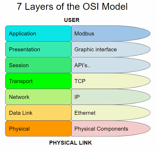
En primer lugar, es muy importante explicar el modelo OSI para comprender todos los elementos que conforman un sistema de telecomunicaciones. El OSI es el modelo de interconexión de sistemas abiertos y este es un modelo conceptual que caracteriza y estandariza las funciones de comunicación de un sistema de telecomunicaciones o informática sin tener en cuenta su estructura interna subyacente. Su objetivo principal es la interoperabilidad de diversos sistemas de comunicación con protocolos de comunicación estándar. Este modelo se divide en siete capas de abstracción diferentes.
Cada capa sirve a la capa de arriba y es servida por la capa debajo de ella. Por ejemplo, una capa que proporciona comunicaciones sin errores a través de una red proporciona la ruta requerida por las aplicaciones por encima de ella, mientras llama a la siguiente capa inferior para enviar y recibir paquetes que constituyen el contenido de esa ruta.
Las diferentes capas son:
-
Capa de aplicación: es la más cercana al usuario, lo que significa que tanto este como el usuario interactúan directamente con la aplicación de software.
-
Capa de presentación: establece el contexto entre las entidades de la capa de aplicación.
-
Capa de sesión: controla las conexiones entre computadoras.
-
Capa de transporte: proporciona los medios funcionales y de procedimiento para transferir secuencias de datos de longitud variable desde un host de origen a un host de destino, manteniendo la calidad de las funciones de servicio.
-
Capa de red: proporciona los medios funcionales y de procedimiento para transferir paquetes de un nodo a otro conectado en diferentes redes.
-
Capa de enlace de datos: proporciona transferencia de datos de nodo a nodo, un enlace entre dos nodos conectados directamente.
-
Capa física: es responsable de la transmisión y recepción de datos brutos no estructurados entre un dispositivo y un medio de transmisión física.
Aquí, podemos ver un esquema de las capas:

Es importante tener en cuenta que hay dos tipos de Modbus; el Modbus TCP que usa Ethernet y está ubicado en la capa 7, y el Modbus 232/485 que usa estos protocolos y está ubicado en todas las capas. Tenemos que tener en cuenta que, muchas veces, las capas de red, datos y física están abarcadas como capas de medios y las otras como capas de host.
Ahora que estamos ubicados, podemos continuar con la explicación principal del video y, si desea descubrir más información relacionada con Ethernet, puede consultar los enlaces que se muestran a continuación.
Enlaces útiles
Material para practicar
-
Arduino Leonardo o Arduino Mega (También puedes utilizar una placa Arduino UNO).
(El equipo utilizado con las placas Arduino Mega y Arduino Leonardo en su interior eran: la familia de PLC Ethernet, el M-Duino21 y los PLC básicos de 20 E / S, el relé Ardbox).
Por favor, contesta esta
Encuesta
y ayúdanos a mejorar el Curso.
#9 EXAMPLES : CONTROLAR ENTRADAS-SALIDAS REMOTAMENTE USANDO ETHERNET
Al leer este capítulo, debe tener en cuenta una serie de puntos:
Puedes practicar con una placa Arduino. En los diferentes PLC utilizamos placas Arduino originales, por este motivo no es necesario que practique con nuestros equipos.
(Recuerde: para nosotros, un PLC funciona como una placa Arduino, nuestros PLC utilizan placas Arduino originales para que pueda probar este curso utilizando placas Arduino originales).
Introducción:
Este es un nuevo capítulo sobre el curso de programación Arduino para uso industrial. En este capítulo veremos un ejemplo sobre cómo administrar las entradas y salidas de un PLC Arduino de forma remota utilizando Ethernet, relacionado con el capítulo anterior. Entonces, hablaremos sobre este ejemplo de control y el protocolo Ethernet.
Hay muchos protocolos diferentes de Ethernet; UDP, por ejemplo, pero el más utilizado es TCP, del cual veremos un ejemplo práctico. Nuestro equipo de programación desarrolló un nuevo protocolo, diseñado para funcionar mejor en nuestro equipo y pensado para nuestros clientes, llamado SimpleComm.
Explicación teórica:
En este capítulo veremos un ejemplo práctico sobre cómo administrar las entradas y salidas de un PLC usando Ethernet. Vamos a utilizar el protocolo TCP para establecer este tipo de comunicación pero, con respecto a esto, tenemos que recordar el modelo OSI explicado en el capítulo anterior y, relacionándolo con nuestro modelo específico, podemos ver un esquema como este:
Example 1:
This type of communication is based in a master and a slave, you can find more information about this kind of relation in this post -> POST Configuration of RS-485 Protocol on Arduino IDE -Configuration of RS-485 Protocol on Arduino IDE
The practical example that we will see in this chapter is based in two post of our blog, divided in salve and master parts:
-How to use TCP Slave library with Arduino based industrial controller
-Modbus TCP Master with Indsutrial Arduino based PLCs
-How to connect Arduino based PLCs using Modbus TCP/IP
Slave:
In this example, as we saw in the previous paragraphs, the Application layer protocol used is Modbus. First of all we have to see some aspects of this to understand the code in a better way.
| Object type | Access | Size |
| Coil | Read-write | 1bit |
| Discrete input | Read | 1 bit |
| Input register | Read | 16 bits |
| Holding registers | Read-write | 16 bits |
Normally coils a are used to write digital values to an outputs. Discrete inputs are used to read digital inputs. Registers are use to communicate data between the devices and also usually used for analog I/Os.
Requirements
Modbus TCP slave functions
The ModbusTCPSlave module implements the Modbus TCP Slave capabilities.
#include <ModbusTCPSlave.h>

ModbusTCPSlave slave;
The default TCP port is the 502 but you can change it with:
// Set the TCP listening port to 510 instead of 502
ModbusTCPSlave slave(510);
To map the coils, discrete inputs, holding registers and input registers addresses with the desired variables values, the module uses four variables arrays:
bool coils[NUM_COILS];
bool discreteInputs[NUM_DISCRETE_INPUTS];
uint16_t holdingRegistesr[NUM_HOLDING_REGISTERS];
uint16_t inputRegisters[NUM_INPUT_REGISTERS];
The lengths of these arrays depend on the application and the registers usages. Obviously, the names of the arrays also depend on your preferences.
To associate the registers arrays with the library it is possible to use these functions in the setup:
slave.setCoils(coils, NUM_COILS);
slave.setDiscreteInputs(discreteInputs, NUM_DISCRETE_INPUTS);
slave.setHoldingRegisters(holdingRegisters, NUM_HOLDING_REGISTERS);
slave.setInputRegisters(inputRegisters, NUM_INPUT_REGISTERS);
It is not required to have all kind of registers mapping to work, only the used by the application.
To start the ModbusTCP server, call the begin function after the registers mapping. It is also possible to call the beginfunction before the registers mapping. Remember to begin the Ethernet before the ModbusTCPSlave object in the setup.
// Init the Ethernet
Ethernet.begin(mac, ip);

// Init the ModbusTCPSlave object
slave.begin();
At this time the ModbusTCP server is running and the only important thing to do is to update the ModbusTCPSlave object often in the loop function, and tret the registers mapping values to update variables, inputs and outputs.
// Update discrete inputs and input registers values
discreteInputs[0] = digitalRead(I0_7);
inputRegisters[0] = analogRead(I0_0);
// ...

// Update the ModbusTCPSlave object
slave.update();

// Update coils and holding registers
digitalWrite(Q0_0, coils[0]);
// ...
Example software for Arduino based automation controller
/*
   Copyright (c) 2018 Boot&Work Corp., S.L. All rights reserved
   This program is free software: you can redistribute it and/or modify
   it under the terms of the GNU Lesser General Public License as published by
   the Free Software Foundation, either version 3 of the License, or
   (at your option) any later version.
   This program is distributed in the hope that it will be useful,
   but WITHOUT ANY WARRANTY; without even the implied warranty of
   MERCHANTABILITY or FITNESS FOR A PARTICULAR PURPOSE.  See the
   GNU Lesser General Public License for more details.
   You should have received a copy of the GNU Lesser General Public License
   along with this program.  If not, see <http://www.gnu.org/licenses/>.
 */
#include <ModbusTCPSlave.h>
#if defined(MDUINO_PLUS)
#include <Ethernet2.h>
#else
#include <Ethernet.h>
#endif
// Ethernet configuration values
uint8_t mac[] = { 0xDE, 0xAD, 0xBE, 0xEF, 0xFE, 0xEE };
IPAddress ip(10, 10, 10, 4);
int port = 502;
// Modbus registers mapping
// This example uses the M-Duino21+ mapping
int digitalOutputsPins[] = {
#if defined(PIN_Q0_4)
  Q0_0, Q0_1, Q0_2, Q0_3, Q0_4,
#endif
};
int digitalInputsPins[] = {
#if defined(PIN_I0_6)
  I0_0, I0_1, I0_2, I0_3, I0_4, I0_5, I0_6,
#endif
};
int analogOutputsPins[] = {
#if defined(PIN_A0_7)
  A0_5, A0_6, A0_7,
#endif
};
int analogInputsPins[] = {
#if defined(PIN_I0_12)
  I0_7, I0_8, I0_9, I0_10, I0_11, I0_12,
#endif
};
#define numDigitalOutputs int(sizeof(digitalOutputsPins) / sizeof(int))
#define numDigitalInputs int(sizeof(digitalInputsPins) / sizeof(int))
#define numAnalogOutputs int(sizeof(analogOutputsPins) / sizeof(int))
#define numAnalogInputs int(sizeof(analogInputsPins) / sizeof(int))
bool digitalOutputs[numDigitalOutputs];
bool digitalInputs[numDigitalInputs];
uint16_t analogOutputs[numAnalogOutputs];
uint16_t analogInputs[numAnalogInputs];
// Define the ModbusTCPSlave object
ModbusTCPSlave modbus(port);
////////////////////////////////////////////////////////////////////////////////////////////////////
void setup() {
  Serial.begin(9600UL);
  // Init variables, inputs and outputs
  for (int i = 0; i < numDigitalOutputs; ++i) {
    digitalOutputs[i] = false;
    digitalWrite(digitalOutputsPins[i], digitalOutputs[i]);
  }
  for (int i = 0; i < numDigitalInputs; ++i) {
    digitalInputs[i] = digitalRead(digitalInputsPins[i]);
  }
  for (int i = 0; i < numAnalogOutputs; ++i) {
    analogOutputs[i] = 0;
    analogWrite(analogOutputsPins[i], analogOutputs[i]);
  }
  for (int i = 0; i < numAnalogInputs; ++i) {
    analogInputs[i] = analogRead(analogInputsPins[i]);
  }
  // Init Ethernet
  Ethernet.begin(mac, ip);
  Serial.println(Ethernet.localIP());
  // Init ModbusTCPSlave object
  modbus.begin();
  modbus.setCoils(digitalOutputs, numDigitalOutputs);
  modbus.setDiscreteInputs(digitalInputs, numDigitalInputs);
  modbus.setHoldingRegisters(analogOutputs, numAnalogOutputs);
  modbus.setInputRegisters(analogInputs, numAnalogInputs);
}
////////////////////////////////////////////////////////////////////////////////////////////////////
void loop() {
  // Update inputs
  for (int i = 0; i < numDigitalInputs; ++i) {
    digitalInputs[i] = digitalRead(digitalInputsPins[i]);
  }
  for (int i = 0; i < numAnalogInputs; ++i) {
    analogInputs[i] = analogRead(analogInputsPins[i]);
  }
  // Process modbus requests
  modbus.update();
  // Update outputs
  for (int i = 0; i < numDigitalOutputs; ++i) {
    digitalWrite(digitalOutputsPins[i], digitalOutputs[i]);
  }
  for (int i = 0; i < numAnalogOutputs; ++i) {
    analogWrite(analogOutputsPins[i], analogOutputs[i]);
  }
}
Referral
M-Duino controller family Tools40 library installed
Master:
Now, taking into account the same Modbus information that we saw in the Slave part and the same Requirements, we are going to see the master part:
Modbus TCP master functions
The functions to read and write slave values are:
readCoils(client, slave_address, address, quantity);
readDiscreteInputs(client, slave_address, address, quantity);
readHoldingRegisters(client, slave_address, address, quantity);
readInputRegisters(client, slave_address, address, quantity);
writeSingleCoil(client, slave_address, address, value);
writeSingleRegister(client, slave_address, address, value);
writeMultipleCoils(client, slave_address, address, values, quantity);
writeMultipleRegisters(client, slave_address, address, values, quantity);
Where
clientis the EthernetClient connected to the slave.slave_addressis the Modbus TCP slave address.addressis the coil, digital input, holding register or input register address. Usually this address is the coil, digital input, holding register or input register number minus 1: the holding register number40009has the address8.quantityis the number of coils, digital inputs, holding registers or input registers to read/write.valueis the given value of the coil or holding registers on a write operation. Depending on the function the data type changes. A coil is represented by aboolvalue and a holding register is represented by auint16_tvalue.
On a multiple read/write function the address argument is the first element address. On a multiple write function the valuesargument is an array of values to write.
It is important to notice that these functions are non-blocking, so they don't return the read value. They return true or falsedepending on the current module state. If there is a pending Modbus request or the client is not connected, they return false.
// Read 5 holding registers from address 0x24 of slave with address 0x10if (master.readHoldingRegisters(client, 0x10, 0x24, 5)) {
	// OK, the request is being processed
} else {
	// ERROR, the master is not in an IDLE state
}
There is the available() function to check for responses from the slave.
ModbusResponse response = master.available();
if (response) {
	// Process response
}
The ModbusResponse implements some functions to get the response information:
hasError();
getErrorCode();
getSlave();
getFC();
isCoilSet(offset);
isDiscreteInputSet(offset);
isDiscreteSet(offset);
getRegister(offset);
ModbusResponse response = master.available();
if (response) {
	if (response.hasError()) {
		// There is an error. You can get the error code with response.getErrorCode()
	} else {
		// Response ready: print the read holding registers
		for (int i = 0; i < 5; ++i) {
			Serial.println(response.getRegister(i);
		}
	}
}
The possible error codes are:
                            0x01 ILLEGAL FUNCTION
0x02 ILLEGAL DATA ADDRESS
0x03 ILLEGAL DATA VALUE
0x04 SERVER DEVICE FAILURE
Software
After seeing the bases of the Modbus TCP Master library we can proceed to develop a code to communicate with another Modbus device in our network. In this code is showed how to read registers and how to write coils from another Modbus TCP/IP slave. This example will write random numbers to digital coils every second and also will read 6 values from the slave every 500 milliseconds.
/*
   Copyright (c) 2018 Boot&Work Corp., S.L. All rights reserved
   This program is free software: you can redistribute it and/or modify
   it under the terms of the GNU Lesser General Public License as published by
   the Free Software Foundation, either version 3 of the License, or
   (at your option) any later version.
   This program is distributed in the hope that it will be useful,
   but WITHOUT ANY WARRANTY; without even the implied warranty of
   MERCHANTABILITY or FITNESS FOR A PARTICULAR PURPOSE.  See the
   GNU Lesser General Public License for more details.
   You should have received a copy of the GNU Lesser General Public License
   along with this program.  If not, see <http://www.gnu.org/licenses/>.
 */
#include <ModbusTCPMaster.h>
#if defined(MDUINO_PLUS)
#include <Ethernet2.h>
#else
#include <Ethernet.h>
#endif

// Ethernet configuration values
uint8_t mac[] = { 0xDE, 0xAD, 0xBE, 0xEF, 0xFE, 0xED };
IPAddress ip(10, 10, 10, 3);
IPAddress slaveIp(10, 10, 10, 4);
uint16_t slavePort = 502;

// Define the ModbusTCPMaster object
ModbusTCPMaster modbus;

// Ethernet client object used to connect to the slave
EthernetClient slave;
uint32_t lastSentTime = 0UL;
uint32_t lastSentTimeReadInputs = 0UL;

////////////////////////////////////////////////////////////////////////////////////////////////////
void setup() {
  Serial.begin(9600UL);
  // Begin Ethernet
  Ethernet.begin(mac, ip);
  Serial.println(Ethernet.localIP());
  // NOTE: it is not necessary to start the modbus master object
}

////////////////////////////////////////////////////////////////////////////////////////////////////
void loop() {
  // Connect to slave if not connected
  // The ethernet connection is managed by the application, not by the library
  // In this case the connection is opened once
  if (!slave.connected()) {
    slave.stop();
    slave.connect(slaveIp, slavePort);
    if (slave.connected()) {
      Serial.println("Reconnected");
    }
  }
  // Send a request every 1000ms if connected to slave
  if (slave.connected()) {
    if (millis() - lastSentTime > 1000) {
      // Set random values
      bool values[5];
      for (int i = 0; i < 5; ++i) {
        values[i] = random() & 0x01;
      }
      // Send a Write Multiple Coils request to the slave with address 31
      // It requests for setting 5 coils starting in address 0
      // IMPORTANT: all read and write functions start a Modbus transmission, but they are not
      // blocking, so you can continue the program while the Modbus functions work. To check for
      // available responses, call modbus.available() function often.
      if (!modbus.writeMultipleCoils(slave, 31, 0, values, 5)) {
        // Failure treatment
        Serial.println("Request fail");
      }
      lastSentTime = millis();
    }
    // Check available responses often
    if (modbus.isWaitingResponse()) {
      ModbusResponse response = modbus.available();
      if (response) {
        if (response.hasError()) {
          // Response failure treatment. You can use response.getErrorCode()
          // to get the error code.
          Serial.print("Error ");
          Serial.println(response.getErrorCode());
        } else {
          Serial.println("Done");
        }
      }
    }

    if (millis() - lastSentTimeReadInputs > 500) {
      // Send a Read Input Registers request to the slave with address 31
      // It requests for 6 registers starting at address 0
      // IMPORTANT: all read and write functions start a Modbus transmission, but they are not
      // blocking, so you can continue the program while the Modbus functions work. To check for
      // available responses, call master.available() function often.
      if (!modbus.readInputRegisters(slave, 31, 0, 6)) {
        // Failure treatment
      }
      lastSentTimeReadInputs = millis();
    }

    if (modbus.isWaitingResponse()) {
      ModbusResponse response = modbus.available();
      if (response) {
        if (response.hasError()) {
          // Response failure treatment. You can use response.getErrorCode()
          // to get the error code.
        } else {
          // Get the input registers values from the response
          Serial.print("Input registers values: ");
          for (int i = 0; i < 6; ++i) {
            Serial.print(response.getRegister(i));
            Serial.print(',');
          }
          Serial.println();
        }
      }
    }
  }
}
Example 2:
Following the previous Slave part of the example and, changing the Master's code a little bit in order to make it more interactive with the user, here we have another example:
Application Architecture
M-Duino master has a an interactive serial menu that allow the user to control the application. The menu has 6 options. The first four options are to control two outputs of the slave, the fifth option is to get the analog inputs or registers from the slave and the last option, sixth, is to get the digital inputs or discrete inputs from the slave.
We use writeSingleCoil(), readInputRegisters() and readDiscreteInputs() functions to communicate to the slave. Then just executing a short for loop depending of which message we have sent, we read the values using response.getRegister() or response.isDiscreteInputSet().
The rest of the code is just Ethernet configurations and Serial commands to debug and make the application more interactive
Software
/*
   Copyright (c) 2018 Boot&Work Corp., S.L. All rights reserved
   This program is free software: you can redistribute it and/or modify
   it under the terms of the GNU Lesser General Public License as published by
   the Free Software Foundation, either version 3 of the License, or
   (at your option) any later version.
   This program is distributed in the hope that it will be useful,
   but WITHOUT ANY WARRANTY; without even the implied warranty of
   MERCHANTABILITY or FITNESS FOR A PARTICULAR PURPOSE.  See the
   GNU Lesser General Public License for more details.
   You should have received a copy of the GNU Lesser General Public License
   along with this program.  If not, see <http://www.gnu.org/licenses/>.
 */
#include <ModbusTCPMaster.h>
#if defined(MDUINO_PLUS)
#include <Ethernet2.h>
#else
#include <Ethernet.h>
#endif
// Ethernet configuration values
uint8_t mac[] = { 0xDE, 0xAD, 0xBE, 0xEF, 0xFE, 0xED };
IPAddress ip(10, 10, 10, 3);
IPAddress slaveIp(10, 10, 10, 4);
uint16_t slavePort = 502;
// Define the ModbusTCPMaster object
ModbusTCPMaster modbus;
//
bool registerSet = 0;
bool discreteSet = 0;
// Ethernet client object used to connect to the slave
EthernetClient slave;
uint32_t lastSentTime = 0UL;
uint32_t lastSentTimeReadInputs = 0UL;
////////////////////////////////////////////////////////////////////////////////////////////////////
void setup() {
  Serial.begin(9600UL);
  // Begin Ethernet
  Ethernet.begin(mac, ip);
  Serial.println(Ethernet.localIP());
  // NOTE: it is not necessary to start the modbus master object
  mainUI();
}
////////////////////////////////////////////////////////////////////////////////////////////////////
void loop() {
  // Connect to slave if not connected
  // The ethernet connection is managed by the application, not by the library
  // In this case the connection is opened once
  if (!slave.connected()) {
    Serial.println("Slave not connected");
    slave.stop();
    slave.connect(slaveIp, slavePort);
    if (slave.connected()) {
      Serial.println("Reconnected");
    }
  }
  // Send a request every 1000ms if connected to slave
  if (slave.connected()) {
    //Serial.println("Slave connected");
  if (Serial.available()) {
      byte chosenOption= Serial.read();
  bool value;
  byte address;
  switch(chosenOption){
      case '1': //set Q0_0 to high
          value = 1;
          address = 0;
          if (!(modbus.writeSingleCoil(slave, 0, address, value))) {
            // Failure treatment
            Serial.println("Request fail");
          }
          Serial.println("Q0_0 set to HIGH");
          break;
      case '2': //set Q0_0 to low
          value = 0;
          address = 0;
          if (!(modbus.writeSingleCoil(slave, 0, address, value))) {
            // Failure treatment
            Serial.println("Request fail");
          }
          Serial.println("Q0_0 set to LOW");
          break;
      case '3': //set Q0_1 to high
          value = 1;
          address = 1;
          if (!(modbus.writeSingleCoil(slave, 0, address, value))) {
            // Failure treatment
            Serial.println("Request fail");
          }
          Serial.println("Q0_1 set to HIGH");
          break;
      case '4':
          value = 0;
          address= 1;
          if (!(modbus.writeSingleCoil(slave, 0, address, value))) {
            // Failure treatment
            Serial.println("Request fail");
          }
          Serial.println("Q0_1 set to LOW");
          break;
      case '5':
          if (!modbus.readInputRegisters(slave, 0, 0, 6)) {
            // Failure treatment
            Serial.println("Error requesting registers");
          }else{registerSet = true;}
          break;
      case '6':
          if (!modbus.readDiscreteInputs(slave, 0, 0, 7)) {
          // Failure treatment
          Serial.println("Error requesting discrete input");
          }else{discreteSet = true;}
          break;
  }
  mainUI();
    }
    if (modbus.isWaitingResponse()) {
      ModbusResponse response = modbus.available();
      if (response) {
        if (response.hasError()) {
          // Response failure treatment. You can use response.getErrorCode()
          // to get the error code.
        }else if (registerSet){
          // Get the input registers values from the response
          Serial.print("Input registers values: ");
          for (int i = 0; i < 6; ++i) {
            Serial.print(response.getRegister(i));
            Serial.print(',');
          }
          registerSet = false;
        } else if(discreteSet) {
          // Get the input registers values from the response
          Serial.print("Input discrete values: [");
          for (int i = 0; i < 7; ++i) {
            Serial.print(response.isDiscreteInputSet(i));
            Serial.print(',');
          }
          Serial.println(']');
          discreteSet = false;
        }
      }
    }
  }
}
////////////////////////////////////////////////////////////////////////////////////////////////////
void mainUI(){
    Serial.println("********************Modbus Test*********************");
    Serial.println("Chose an option:");
    Serial.println("1. Set Q0_0 to HIGH");
    Serial.println("2. Set Q0_0 to LOW");
    Serial.println("3. Set Q0_1 to HIGH");
    Serial.println("4. Set Q0_1 to LOW");
    Serial.println("5. Print slave input analog values");
    Serial.println("6. Print slave input digital values");
    Serial.println("****************************************************");
}
Useful links:
Material to practice:
- Arduino Leonardo or Arduino Mega (You can also use an Arduino UNO board if you have one).
(The equipment used with the Arduino Mega and Arduino Leonardo boards inside it were: the Ethernet PLC family, the M-duino21 and the basic 20 I / Os PLCs, the Ardbox Relay).
Please, answer this Survey and help us to improve the Course.
#10 Serial TTL, RS232, RS485
Las comunicaciones en el PLC de Arduino son uno de los puntos más destacados a considerar porque es uno de sus puntos fuertes y, en relación con esto, hay muchos protocolos de comunicación diferentes. En este capítulo, veremos tres tipos diferentes de los principales protocolos de comunicación; Serial TTL, RS-232 y RS-485.
Serial TTL es un tipo de comunicación TTL (Transistor-Transistor Logic) en serie. TTL es una familia lógica de transistores de unión bipolar. Este transistor realiza la lógica y la función de amplificación también.
RS-232 es otro estándar para la transmisión de datos en comunicación en serie. Define formalmente las señales que se conectan entre DTE (equipo terminal de datos), como un terminal de computadora, y un DCE (equipo de terminación de circuito de datos o equipo de comunicación de datos), como un módem.
RS-485 es, una vez más, un estándar para sistemas de comunicación en serie en los que la señalización eléctrica está equilibrada y se admiten sistemas multipunto. Las redes de comunicaciones digitales que implementan el estándar se pueden usar de manera efectiva a largas distancias y en entornos eléctricamente ruidosos. Se pueden conectar múltiples receptores a dicha red en un bus lineal de múltiples líneas.
Con la información que se muestra en esta introducción, podemos proceder a ver el video.
Ahora que estamos ubicados, podemos continuar con la explicación principal del video y, si desea descubrir más información relacionada con Ethernet, puede consultar los enlaces que se muestran a continuación.
Enlaces útiles
Material para practicar
-
Arduino Leonardo o Arduino Mega (También puedes utilizar una placa Arduino UNO si la tienes).
(El equipo utilizado con las placas Arduino Mega y Arduino Leonardo en su interior eran: la familia de PLC Ethernet, el M-Duino21 y los PLC básicos de 20 E / S, el relé Ardbox).
Por favor, contesta esta
Survey
y ayúdanos a mejorar el Curso.