
Index
1. Introduction
2. Requirements
3. Example explanation
3.1 ESP32 code
3.2 M-Duino code
4. Demonstration
4.1 M-Duino instructions
4.2 ESP32 instructions
5. Related links
Introduction
In this post, we are going to see how to use a M-Duino WiFi as an Access Point for a Web Server. We will learn a way in which we do not need to be connected to a router to control the M-Duino. So the M-Duino, specifically the ESP32 board inside of it, does not connect further to a wired network (like a router), it is called soft-AP (soft Acces Point). In this example, we will use an M-Duino 21+ with WiFi/BLE but you can use any model of our WiFi/BLE family.
Requirements
Here you have the link to check out the available devices with these characteristics and the one to download our Inudstrial Shields Boards:
- WiFi & Bluetooth Controller Familiy
- Installing the Industrial Shields Boards in the Arduino IDE (Updated)
Example Explanation
First of all, we have to understand how the PLC board MEGA2560 and the WiFi module ESP32 are connected and how they communicate with each other. Here we have an scheme to visualize the internal connections between the ESP32 Devkit V1 module and the Internal Arduino Mega2560:

ESP32 code
In this part of the program, we will see how the Access Point is implemented. First of all, the WiFi.h library has to be included to work with certain functions of this module. After this, the code initialize all the variables.
In the setup block, it initialize the Serial ports, executes the function for connecting to Wi-Fi network with an SSID and a password, configuring the IP adress too and it begins the server.
In the loop block, after all the proper initializations, there is a conditional structure with whiles and ifs used to manage the client connections and, after this, there is one of the most important parts; the one that turns the GPIOs on and off. In this, depending on the header index of the server page, if one of the outputs (Q0_0 or Q0_1) is turned on or off, the variable var changes its value, the output state properly changes and the state number is written on the Serial2 port (to send it to the Arduino MEGA). Take into account that the state numbers are the following:
0 ---> Q0_0 off 8 ---> Q0_1 off
1 ---> Q0_1 on 9 ---> Q0_1 on
After all these commands, the following ones are used to display the HTML web page and to manage the clients and the buttons interactions. Finally, the connection is closed with client.stop().
Here you have the code:
/*
   Copyright (c) 2019 Boot&Work Corp., S.L. All rights reserved

   This program is free software: you can redistribute it and/or modify
   it under the terms of the GNU Lesser General Public License as published by
   the Free Software Foundation, either version 3 of the License, or
   (at your option) any later version.

   This program is distributed in the hope that it will be useful,
   but WITHOUT ANY WARRANTY; without even the implied warranty of
   MERCHANTABILITY or FITNESS FOR A PARTICULAR PURPOSE.  See the
   GNU Lesser General Public License for more details.

   You should have received a copy of the GNU Lesser General Public License
   along with this program.  If not, see <http://www.gnu.org/licenses/>.
 */

//ESP32 code

// Load Wi-Fi library
#include <WiFi.h>

// Replace with your network credentials
const char* ssid     = "ESP32-Access-Point";
const char* password = "123456789";

// Set web server port number to 80
WiFiServer server(80);

// Variable to store the HTTP request
String header;

// Auxiliar variables to store the current output state
String outputQ0_0State = "off";
String outputQ0_1State = "off";

void setup() {
  Serial.begin(115200UL);
  Serial2.begin(115200UL);

  // Connect to Wi-Fi network with SSID and password
  Serial.print("Setting AP (Access Point)…");
  // Remove the password parameter, if you want the AP (Access Point) to be open
  WiFi.softAP(ssid, password);

  IPAddress IP = WiFi.softAPIP();
  Serial.print("AP IP address: ");
  Serial.println(IP);

  server.begin();
}

void loop(){
  int var;
  WiFiClient client = server.available();   // Listen for incoming clients

  if (client) {                             // If a new client connects,
    Serial.println("New Client.");          // print a message out in the serial port
    String currentLine = "";                // make a String to hold incoming data from the client
    while (client.connected()) {            // loop while the client's connected
      if (client.available()) {             // if there's bytes to read from the client,
        char c = client.read();             // read a byte, then
        Serial.write(c);                    // print it out the serial monitor
        header += c;
        if (c == '\n') {                    // if the byte is a newline character
          // if the current line is blank, you got two newline characters in a row.
          // that's the end of the client HTTP request, so send a response:
          if (currentLine.length() == 0) {
            // HTTP headers always start with a response code (e.g. HTTP/1.1 200 OK)
            // and a content-type so the client knows what's coming, then a blank line:
            client.println("HTTP/1.1 200 OK");
            client.println("Content-type:text/html");
            client.println("Connection: close");
            client.println();

            // turns the GPIOs on and off
            if (header.indexOf("GET /Q0_0/on") >= 0) {
              var=1;//1=Q0_0 on
              Serial.println("1");
              outputQ0_0State="on";
              Serial2.write(1);
            }
            else if (header.indexOf("GET /Q0_0/off") >= 0) {
              var=0;//0=Q0_0 off
              Serial.println("0");
              outputQ0_0State="off";
              Serial2.write(0);
            }
            else if (header.indexOf("GET /Q0_1/on") >= 0) {
              var=9;//9=Q0_1 on
              Serial.println("9");
              outputQ0_1State="on";
              Serial2.write(9);
            }
            else if (header.indexOf("GET /Q0_1/off") >= 0) {
              var=8;//8=Q0_1 off
              Serial.println("8");
              outputQ0_1State="off";
              Serial2.write(8);
            }

            // Display the HTML web page
            client.println("<!DOCTYPE html><html>");
            client.println("<head><meta name=\"viewport\" content=\"width=device-width, initial-scale=1\">");
            client.println("<link rel=\"icon\" href=\"data:,\">");
            // CSS to style the on/off buttons
            // Feel free to change the background-color and font-size attributes to fit your preferences
            client.println("<style>html { font-family: Helvetica; display: inline-block; margin: 0px auto; text-align: center;}");
            client.println(".button { background-color: #4CAF50; border: none; color: white; padding: 16px 40px;");
            client.println("text-decoration: none; font-size: 30px; margin: 2px; cursor: pointer;}");
            client.println(".button2 {background-color: #555555;}</style></head>");

            // Web Page Heading
            client.println("<body><h1>ESP32 Web Server</h1>");

            // Display current state, and ON/OFF buttons for GPIO Q0_0
            client.println("<p>GPIO Q0_0 - State " + outputQ0_0State + "</p>");
            // If the Q0_0 is off, it displays the ON button
            if (outputQ0_0State=="off") {
              client.println("<p><a href=\"/Q0_0/on\"><button class=\"button\">ON</button></a></p>");
            } else {
              client.println("<p><a href=\"/Q0_0/off\"><button class=\"button button2\">OFF</button></a></p>");
            }

            // Display current state, and ON/OFF buttons for GPIO Q0_1
            client.println("<p>GPIO Q0_1 - State " + outputQ0_1State + "</p>");
            // If the Q0_1 is off, it displays the ON button
            if (outputQ0_1State=="off") {
              client.println("<p><a href=\"/Q0_1/on\"><button class=\"button\">ON</button></a></p>");
            } else {
              client.println("<p><a href=\"/Q0_1/off\"><button class=\"button button2\">OFF</button></a></p>");
            }
            client.println("</body></html>");

            // The HTTP response ends with another blank line
            client.println();
            // Break out of the while loop
            break;
          } else { // if you got a newline, then clear currentLine
            currentLine = "";
          }
        } else if (c != '\r') {  // if you got anything else but a carriage return character,
          currentLine += c;      // add it to the end of the currentLine
        }
      }
    }
    // Clear the header variable
    header = "";
    // Close the connection
    client.stop();
    Serial.println("Client disconnected.");
    Serial.println("");
  }
}
M-DUINO code
This program is much easier than the previous one because here, the main point is to, from the point of view of the MEGA shield, receive the correct messages from the ESP32 and, depending on these, activate the proper outputs.
In the setup block, the Serial ports are initialized as well as the output variables as outputs and, both are set to LOW as the initial state.
In the loop block, there is a conditional structure only executed if the Serial1 is available, every time this port receives data. If this condition is true, the Serial1 reads the received order and a switch case structure is executed to deal with it; like we previously said, if the order received is a 0, a digitalWrite of Q0_0 is set to LOW, if it is a 1, Q0_0 is set to HIGH, if this is an 8, Q0_1 is set to LOW and if it is a 9, Q0__1 is set to HIGH.
Here you have the code:
/*
   Copyright (c) 2019 Boot&Work Corp., S.L. All rights reserved

   This program is free software: you can redistribute it and/or modify
   it under the terms of the GNU Lesser General Public License as published by
   the Free Software Foundation, either version 3 of the License, or
   (at your option) any later version.

   This program is distributed in the hope that it will be useful,
   but WITHOUT ANY WARRANTY; without even the implied warranty of
   MERCHANTABILITY or FITNESS FOR A PARTICULAR PURPOSE.  See the
   GNU Lesser General Public License for more details.

   You should have received a copy of the GNU Lesser General Public License
   along with this program.  If not, see <http://www.gnu.org/licenses/>.
 */

// M-Duino code
#include <WifiModule.h>

void setup() {
  Serial.begin(115200UL);
  WifiModule.begin(115200UL);
  // Initialize the output variables as outputs
  pinMode(Q0_0, OUTPUT);
  pinMode(Q0_1, OUTPUT);
  // Set outputs to LOW
  digitalWrite(Q0_0, LOW);
  digitalWrite(Q0_1, LOW);
}

void loop(){
  int order;
  if (WifiModule.available()){
    order=WifiModule.read();
    Serial.println(order);

    switch(order){
      case 0:
        digitalWrite(Q0_0, LOW);
        break;
      case 1:
        digitalWrite(Q0_0, HIGH);
        break;
      case 8:
        digitalWrite(Q0_1, LOW);
        break;
      case 9:
        digitalWrite(Q0_1, HIGH);
        break;
    }
  }
}
Demonstration
First of all, we properly select the correct devices and upload both codes.
M-Duino instructions:


.jpg?access_token=f20ad2d6-9169-45c0-afce-a73afc991500 "M-Duino 3 - Using a M-Duino WiFi as an Access Point")
ESP32 instructions:
.jpg?access_token=7f0e83ad-d015-45da-ab45-42f26710409d "M-Duino 4 - Using a M-Duino WiFi as an Access Point")

Take into account that you can customize the SSID and the password as well:
// Replace with your network credentials
const char* ssid     = "ESP32-Access-Point";
const char* password = "123456789";
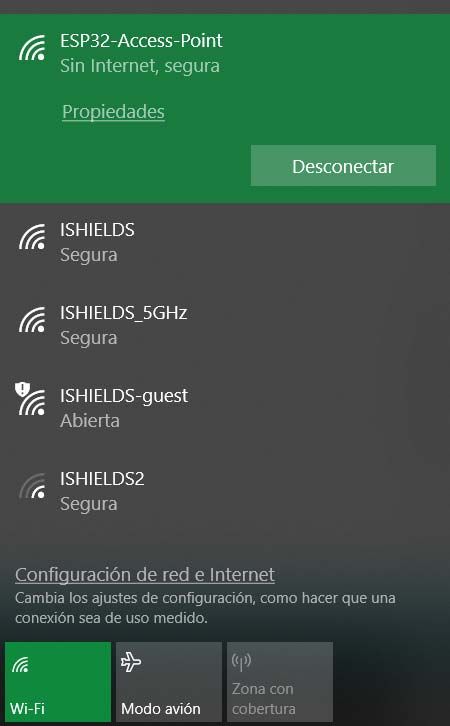
After uploading both codes, you have to open your WiFi configuration and connect your device (the one that you want to use to control the M-Duino, a PC in our example) to the ESP32-Access-Point. The password is 123456789 but you can change it as the network name as we previously saw.
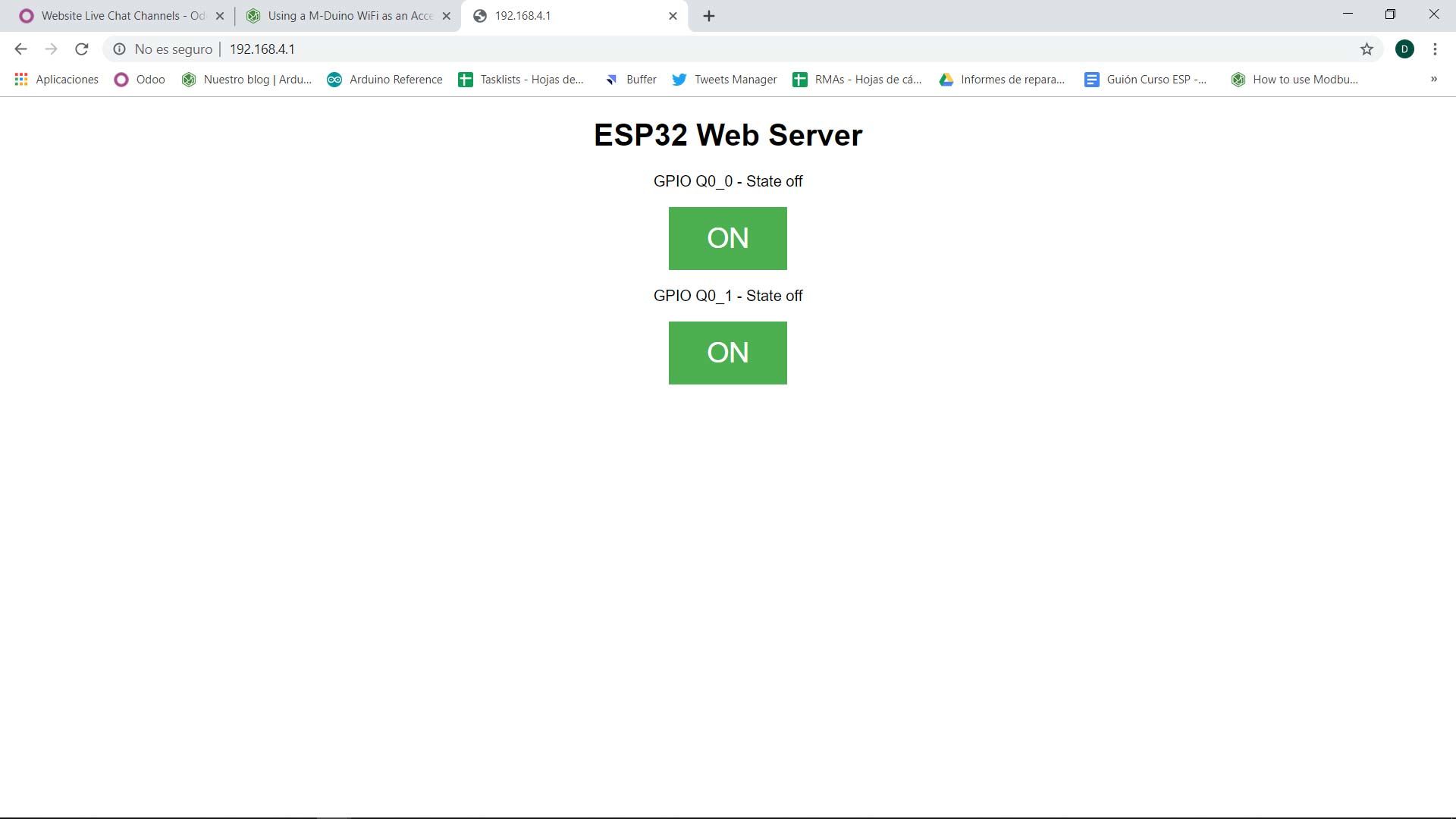
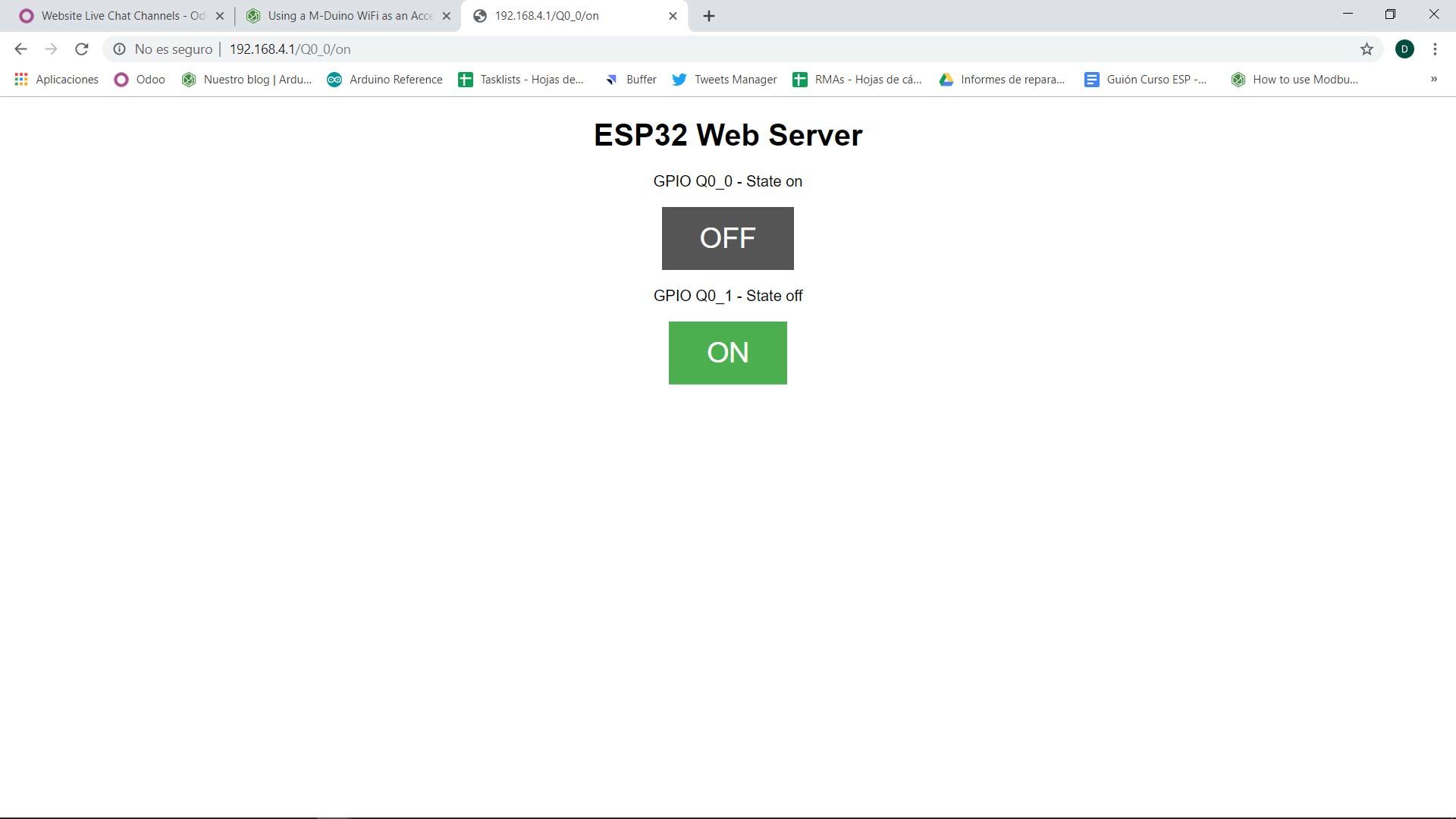
At this point, you have to open your browser and put this IP: 192.168.4.1 to see the ESP32 Web Server. And now, you can control the Q0_0 and Q0_1 outputs of your M-Duino device remotely using this server, with your favorite device and from several points simultaneously.
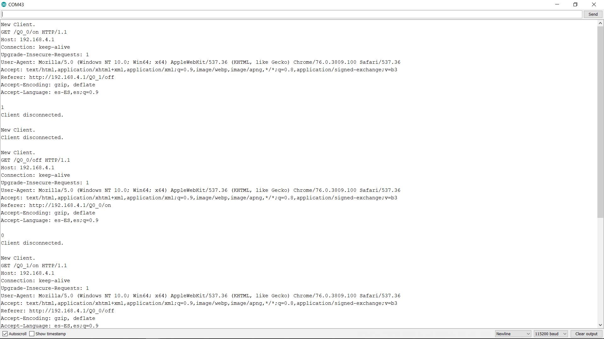
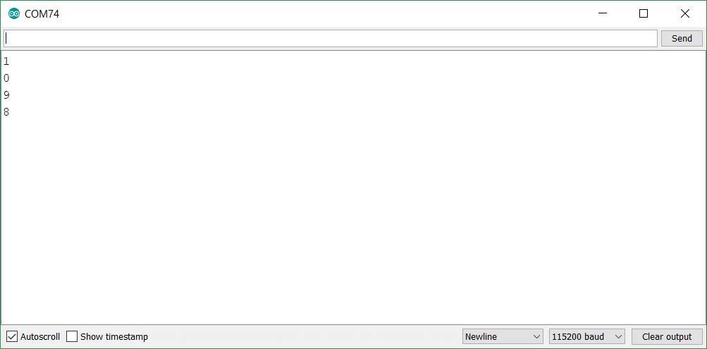
If you open the Serial Monitor of the ESP32 port (be sure to configure the same BaudRate as the code) you can check all the client's information and the outputs connections/disconnections (the state number).
If you open the Serial Monitor of the M-Duino port (be sure to configure the same BaudRate as the code) you can check the outputs connections/disconnections (the state number).
Using a M-Duino WiFi as an Access Point