
INTRODUCTION
The Read Multiple Holding Registers Modbus RTU function (Modbus Function Code: 3), is used to read the contents of a contiguous block of holding registers in a remote device.
In this blog post, we will be reading multiple holding registers between Arduino based PLC set as client - server >
MODBUS RTU
To know more about Modbus RTU and how the library works, please visit the following blog post:
HARDWARE REQUIREMENTS
- 2x M-Duino PLC >
- Power Supply >
- B type cable, to program the Arduino based PLC
- Two twisted pair cables, for RS485.
SOFTWARE REQUIREMENTS
CONNECTIONS
Now, in order to set a Modbus RTU communication, we are going to do the following:
1. Power the PLC between 12 and 24V.
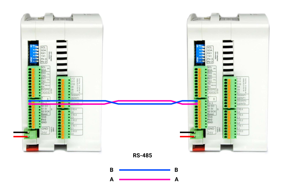
2. Wire the cables through RS-485. This is based on a twisted pair cables, on cable from A+ to A+, and the other one from B- to B-.
3. Set the red switch to the Half-Duplex: HD
MODBUS RTU MASTER READ MULTIPLE HOLDING REGISTERS
In order to set an M-Duino as a master and the other one as a slave, we will have to program both to execute each code. So, in order to program the master, open up a new file of Arduino IDE, and paste the code below:
/*
   Copyright (c) 2018 Boot&Work Corp., S.L. All rights reserved

   This program is free software: you can redistribute it and/or modify
   it under the terms of the GNU Lesser General Public License as published by
   the Free Software Foundation, either version 3 of the License, or
   (at your option) any later version.

   This program is distributed in the hope that it will be useful,
   but WITHOUT ANY WARRANTY; without even the implied warranty of
   MERCHANTABILITY or FITNESS FOR A PARTICULAR PURPOSE.  See the
   GNU Lesser General Public License for more details.

   You should have received a copy of the GNU Lesser General Public License
   along with this program.  If not, see <http://www.gnu.org/licenses/>.
*/

#include <ModbusRTUMaster.h>

// Define the ModbusRTUMaster object, using the RS-485 or RS-232 port (depending on availability)
#if defined HAVE_RS485_HARD
#include <RS485.h>
ModbusRTUMaster master(RS485);

#elif defined HAVE_RS232_HARD
#include <RS232.h>
ModbusRTUMaster master(RS232);

#else
ModbusRTUMaster master(Serial1);
#endif

uint32_t lastSentTime = 0UL;
const uint32_t baudrate = 38400UL;

////////////////////////////////////////////////////////////////////////////////////////////////////
void setup() {
  Serial.begin(9600UL);

  // Start the serial port
#if defined HAVE_RS485_HARD
  RS485.begin(baudrate, HALFDUPLEX, SERIAL_8E1);
#elif defined HAVE_RS232_HARD
  RS232.begin(baudrate, SERIAL_8E1);
#else
  Serial1.begin(baudrate, SERIAL_8E1);
#endif

  // Start the modbus master object.
  // It is possible to define the port rate (default: 19200)
  master.begin(baudrate);
}

////////////////////////////////////////////////////////////////////////////////////////////////////
void loop() {
  // Send a request every 1000ms
  if (millis() - lastSentTime > 1000) {
    // Send a Write Single Register request to the slave with address 31
    // It writes the value of 1000 to the register starting at address 0
    // IMPORTANT: all read and write functions start a Modbus transmission, but they are not
    // blocking, so you can continue the program while the Modbus functions work. To check for
    // available responses, call master.available() function often.
    if (!master.readHoldingRegisters(31, 0, 3)) {
      // Failure treatment
    }

    lastSentTime = millis();
  }

  // Check available responses often
  if (master.isWaitingResponse()) {
    ModbusResponse response = master.available();
    if (response) {
      if (response.hasError()) {
        // Response failure treatment. You can use response.getErrorCode()
        // to get the error code.
        Serial.print("Error ");
        Serial.println(response.getErrorCode());
      } else {
        // Get the discrete inputs values from the response
        if (response.hasError()) {
          // Response failure treatment. You can use response.getErrorCode()
          // to get the error code.
          Serial.print("Error ");
          Serial.println(response.getErrorCode());
        } else {
          Serial.print("Holding Register values: ");
          for (int i = 0; i < 3; ++i) {
            Serial.print(response.getRegister(i));
            Serial.print(',');
          }
          Serial.println();
        }
      }
    }
  }
}
1. Once the sketch is opened, click on Tools > Board > Industrial Shields boards > And select the M-Duino family.
2. Then, select the PLC model by going to Tools > Model > And selecting the model. In our case: M-Duino 21+
3. Select the port by going to Tools > Port > And select the port of the Arduino board.
4. Finally, either click on the arrow to upload the sketch, or go to Sketch > Upload.
MODBUS RTU SLAVE
Once the master is already programmed, we are going to do the same as with the Master PLC, but choosing the ModbusRTUSlave sketch. So:
1. Change the B type cable and connect it to the other M-Duino PLC.
2. Go to the top bar, and click on: File > Examples > Modbus > and select the ModbusRTUSlave sketch.
3. Once the sketch is opened, click on Tools > Board > Industrial Shields boards > And select the M-Duino family.
4. Then, select the PLC model by going to Tools > Model > And selecting the model. In our case: M-Duino 21+
5. Select the port by going to Tools > Port > And select the port of the Arduino board.
6. Finally, either click on the arrow to upload the sketch, or go to Sketch > Upload.
TESTING
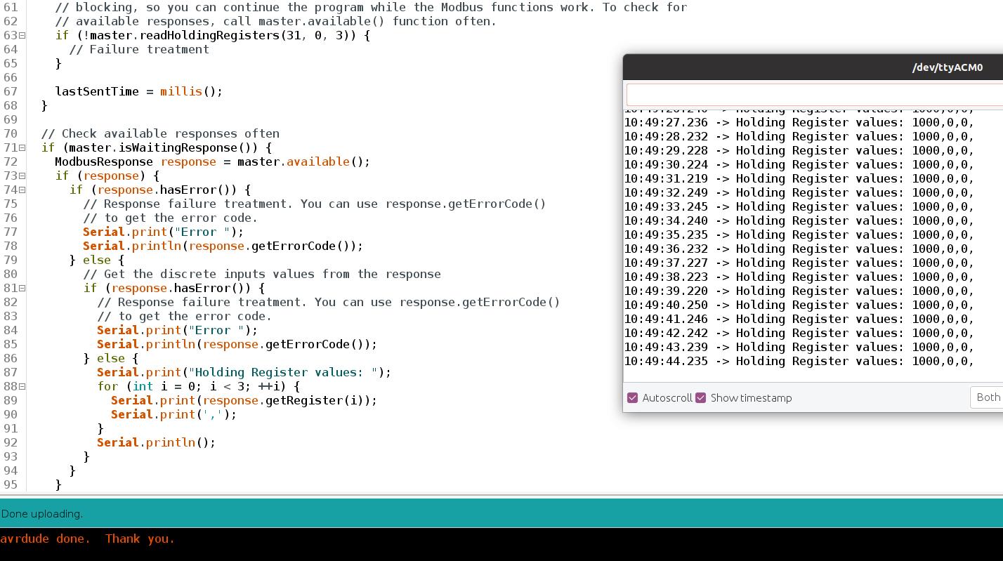
Before following this blog post, we set a Single Holding Register > to 1000.
Now, we can see that the value of the first holding register, is 1000:
Modbus RTU Tutorial: How to Read Holding Registers with M-Duino PLC