Develop your SCADA Application based on NodeRED
Course 10 Chapters of General Content [IS.AC002.GC]
How to install Node Red (PC and Raspberry Pi)
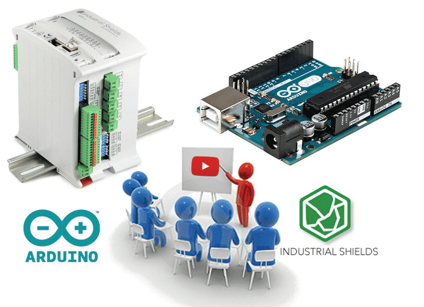
NodeRED is a open source programming tool, based in NodeJS, to develop applications in order to interact with different hardware's. Also Node-RED provide a browser editor that make easier to program and configure your own applications.
See more information of Node-RED in the official website: Node-RED about
The first step of this course w ill be how to install NodeRed application in your personal computer. Before install Node-RED we must install NodeJS.
HOW TO INSTALL NODEJS:
Just go the official website of NodeJS and download the NodeJS source code or a pre-build installer for your OS: NodeJS Download
If you want to install it from the Linux command line:
Add the repository:
sudo apt install curl
For the latest release, type:
curl -sL https://deb.nodesource.com/setup_10.x | sudo bash -
For the LTS release, type:
curl -sL https://deb.nodesource.com/setup_8.x | sudo bash -
Finally to install NODEJS type:
sudo apt install nodejs
HOW TO INSTALL NODE-RED:
After installing the NodeJS our computer is ready to install Node-RED. The best way to install Node-RED is to use the node packae manager, npm, that already comes with Node.js.
WINDOWS OS:
Type to the command prompt:
npm install -g --unsafe-perm node-red
LINUX OS:
Type to command line:
sudo npm install -g --unsafe perm node-red
Take a look on the official installation guide to know more details: Node-RED install
Once you have installed the Node-RED you are able to proceed with the next chapter of the course,
and now we will see how to install Node Red on your Raspberry Pi.
Install Node Red on your Raspberry Pi
The content of this chapter is how to install our NodeRED application to one of our Touchberry Pi or other Panels PC based in Linux. This type of applications are very used for our customers because it's a easy and robust way to have a SCADA touch panel next to the installation. Another point that we will focus during the chapter is how to add the autostart capability, so once we torn on the panel the system will show us directly the NodeRED application.
Installation and Upgrade
Depending which version of Panel PC we will have installed different version of Debian or Ubuntu. Upgrade or install the last version of NodeRED into your system typing in the terminal:
bash <(curl -sL https://raw.githubusercontent.com/node-red/raspbian-deb-package/master/resources/update-nodejs-and-nodered)
Update npm before installing any package using the following comands:
cd ~/.node-red npm outdated npm update
Running NodeRED
To start NodeRED open a new terminal window and type:
node-red-start
*Closing the terminal or ctrl-c does not stop the NodeRED running. It will continue running in the background.
To stop, type:
node-red-stop
Autostart on boot
Probably in your application you will want that the NodeRED start when you turn on your Touchberry Pi. In order to do that we will open the terminal again and type:
sudo systemctl enable nodered.service
and to disable type:
sudo systemctl disable nodered.service
These are the basics to install NodeRED to our Touchberry Pi or other Linux based Industrial Shields panel PC.
If you need additional information about that follow the next link.
Do you want to continue the course?...for free!!!
If you are interested in
You will receive a weekly chapter to develop a NodeRed's Scada Application.
Industrial Applications can run under Open Source Platforms
MQTT client for Arduino based PLC as a I/Os module.
In the chapter #1 is explained how to configure your Industrial Arduino based PLC as a MQTT I/Os Module.
Before starting this chapter will be interesting to take a look
After that, take a fast look on the next libraries:
-
MQTT: MQTT Post
-
ArduinoJson: ArduinoJson library
The architecture of the code is made for
These arrays are: digitalOutputs , analogOutputs, digitalInputs, analogInputs
So, every array will be structured as follows:
digitalOutputs[NUM_ZONES][NUM_DIGITAL_OUTPUTS_PER_ZONE] = {{Q0_0, Q0_1... }, {Q1_0, Q1_1...}, {Q2_0, Q2_1...}
This last example will be for a M-Duino 58+, every zone is subdivided with their related pins nomenclature.
After explained how to access to the inputs mapping we are ready to explain the rest of the code.
In the setup() we just are making the initialization of the Ethernet and MQTT client called mqtt, relating the callback function when we receive a message through MQTT and all the actual input values. After that we just have three main functions in the loop() function. We are calling the reconnect() function if there is no connection with the server,if there is connection we are just using the mqtt.loop() function that will maintain the connectivity with our server. Apart of this twofunctions we have the updateInputs() that will update the real value of the inputs.
Lets go deeper in the functions to have a better understating of what they do:
-
OUTPUTS MANAGEMENT:
Firs of all, we have the reconnect() function that will subscribe to the "Q" and "A" topics. One topic is dedicated to analog outputs and the other is dedicated to the digital outputs. If is not connected to the server, then they will stop the client connection in order to not cause any issue with the server ports.
Second, to understand how the outputs control works we need to look into the callback function. In this program the callback function is receiveMqttMessage(). The receiveMqttMessage() function will run every time that we receive a message. So, when we receive a message the callback function will decide if the topic is for analog or digital pins and then will call the right function for it,
The setAnalogOutput() function work exactly the in the same way that setDigitalOutput().
ANALOG_OUTPUTS_OFFSET is used to offset the value of the analog pins. Analog pins are placed in the positions 5, 6 ,7. This is why the ANALOG_OUTPUTS_OFFSET is 5.
-
INPUT MANAGEMENT:
In the main loop we have the function updateInputs() that will update all the values of the inputs. This function will be comparing all the previous values to the current ones and if the new value have changed, then the program will publish the new value though MQTT. The digital values will be compering if there is a 0 or a 1, the function that make this work is updateDigitalInput().
In the analog site the program will compare if the analog value
/*
   Copyright (c) 2019 Boot&Work Corp., S.L. All rights reserved
   This program is free software: you can redistribute it and/or modify
   it under the terms of the GNU Lesser General Public License as published by
   the Free Software Foundation, either version 3 of the License, or
   (at your option) any later version.
   This program is distributed in the hope that it will be useful,
   but WITHOUT ANY WARRANTY; without even the implied warranty of
   MERCHANTABILITY or FITNESS FOR A PARTICULAR PURPOSE.  See the
   GNU Lesser General Public License for more details.
   You should have received a copy of the GNU Lesser General Public License
   along with this program.  If not, see <http://www.gnu.org/licenses/>.
 */

// included library depending of M-Duino version
#ifdef MDUINO_PLUS
#include <Ethernet2.h>
#else
#include <Ethernet.h>
#endif

// libraries needed for MQTT communication
#include <ArduinoJson.h>
#include <PubSubClient.h>
#define MQTT_ID "demo"
#define NUM_ZONES 1
#define NUM_DIGITAL_OUTPUTS_PER_ZONE 5
#define DIGITAL_OUTPUTS_OFFSET 0

const int digitalOutputs[NUM_ZONES][NUM_DIGITAL_OUTPUTS_PER_ZONE] = {
  {Q0_0, Q0_1, Q0_2, Q0_3, Q0_4},
};
#define NUM_ANALOG_OUTPUTS_PER_ZONE 3
#define ANALOG_OUTPUTS_OFFSET 5

const int analogOutputs[NUM_ZONES][NUM_DIGITAL_OUTPUTS_PER_ZONE] = {
  {A0_5, A0_6, A0_7},
};
#define NUM_DIGITAL_INPUTS_PER_ZONE 7
#define DIGITAL_INPUTS_OFFSET 0

const int digitalInputs[NUM_ZONES][NUM_DIGITAL_INPUTS_PER_ZONE] = {
  {I0_0, I0_1, I0_2, I0_3, I0_4, I0_5, I0_6},
};
#define NUM_ANALOG_INPUTS_PER_ZONE 6
#define ANALOG_INPUTS_OFFSET 7
#define ANALOG_INPUTS_THRESHOLD 5 // Filtering threshold

const int analogInputs[NUM_ZONES][NUM_ANALOG_INPUTS_PER_ZONE] = {
  {I0_7, I0_8, I0_9, I0_10, I0_11, I0_12},
};
byte mac[] = { 0xDE, 0xED, 0xBA, 0xFE, 0xFE, 0xAE };
IPAddress broker(10, 0, 3, 21);
unsigned port = 1883;
// Initialize client
EthernetClient client;
PubSubClient mqtt(client);
int digitalInputsValues[NUM_ZONES][NUM_DIGITAL_INPUTS_PER_ZONE];
int analogInputsValues[NUM_ZONES][NUM_ANALOG_INPUTS_PER_ZONE];

////////////////////////////////////////////////////////////////////////////////////////////////////
void setup(){
  Ethernet.begin(mac);
  mqtt.setServer(broker, port);
  mqtt.setCallback(receiveMqttMessage);
  // Init variables
  for (int i = 0; i < NUM_ZONES; ++i) {
    for (int j = 0; j < NUM_DIGITAL_INPUTS_PER_ZONE; ++j) {
      digitalInputsValues[i][j] = digitalRead(digitalInputs[i][j]);
    }
    for (int j = 0; j < NUM_ANALOG_INPUTS_PER_ZONE; ++j) {
      analogInputsValues[i][j] = analogRead(analogInputs[i][j]);
    }
  }
}

////////////////////////////////////////////////////////////////////////////////////////////////////
void loop() {
  if (!mqtt.connected()) {
    reconnect();
  } else {
    mqtt.loop();
  }
  updateInputs();
}

////////////////////////////////////////////////////////////////////////////////////////////////////
void updateInputs() {
  for (int i = 0; i < NUM_ZONES; ++i) {
    for (int j = 0; j < NUM_DIGITAL_INPUTS_PER_ZONE; ++j) {
      updateDigitalInput(i, j);
    }
    for (int j = 0; j < NUM_ANALOG_INPUTS_PER_ZONE; ++j) {
      updateAnalogInput(i, j);
    }
  }
}

////////////////////////////////////////////////////////////////////////////////////////////////////
void updateDigitalInput(int zone, int index) {
  int value = digitalRead(digitalInputs[zone][index]);
  if (value != digitalInputsValues[zone][index]) {
    digitalInputsValues[zone][index] = value;
    publishInput(zone, index + DIGITAL_INPUTS_OFFSET, value);
  }
}

////////////////////////////////////////////////////////////////////////////////////////////////////
void updateAnalogInput(int zone, int index) {
  int value = analogRead(analogInputs[zone][index]);
  int minValue = value > ANALOG_INPUTS_THRESHOLD ? value - ANALOG_INPUTS_THRESHOLD : 0;
  int maxValue = value < 1023 - ANALOG_INPUTS_THRESHOLD ? value + ANALOG_INPUTS_THRESHOLD : 1023;
  if ((analogInputsValues[zone][index] < minValue) || (analogInputsValues[zone][index] > maxValue)) {
    analogInputsValues[zone][index] = value;
    publishInput(zone, index + ANALOG_INPUTS_OFFSET, value);
  }
}

////////////////////////////////////////////////////////////////////////////////////////////////////
void setDigitalOutput(char *payload, unsigned int len) {
  DynamicJsonBuffer json(JSON_OBJECT_SIZE(3));
  JsonObject &root = json.parseObject(payload, len);
  if (root.success()) {
    int zone = root["zone"];
    if (zone >= NUM_ZONES) {
      // Invalid zone
      return;
    }
    int index = root["index"];
    index -= DIGITAL_OUTPUTS_OFFSET;
    if (index >= NUM_DIGITAL_OUTPUTS_PER_ZONE) {
      // Invalid digital output
      return;
    }
    int value = root["value"];
    digitalWrite(digitalOutputs[zone][index], value);
  }
}

////////////////////////////////////////////////////////////////////////////////////////////////////
void setAnalogOutput(char *payload, unsigned int len) {
  DynamicJsonBuffer json(JSON_OBJECT_SIZE(3));
  JsonObject &root = json.parseObject(payload, len);
  if (root.success()) {
    int zone = root["zone"];
    if (zone >= NUM_ZONES) {
      // Invalid zone
      return;
    }
    int index = root["index"];
    index -= ANALOG_OUTPUTS_OFFSET;
    if (index >= NUM_ANALOG_OUTPUTS_PER_ZONE) {
      // Invalid analog output
      return;
    }
    int value = root["value"];
    analogWrite(analogOutputs[zone][index], value);
  }
}

////////////////////////////////////////////////////////////////////////////////////////////////////
void reconnect() {
  if (mqtt.connect(MQTT_ID)) {
    mqtt.subscribe("Q");
    mqtt.subscribe("A");
  } else {
    // MQTT connect fail
    client.stop();
  }
}

////////////////////////////////////////////////////////////////////////////////////////////////////
void receiveMqttMessage(char* topic, byte* payload, unsigned int len) {
  if (strcmp(topic, "Q") == 0) {
    // Set digital output
    setDigitalOutput((char*) payload, len);
  } else if (strcmp(topic, "A") == 0) {
    // Set analog output
    setAnalogOutput((char*) payload, len);
  }
}

////////////////////////////////////////////////////////////////////////////////////////////////////
void publishInput(int zone, int index, int value) {
  DynamicJsonBuffer json(JSON_OBJECT_SIZE(3));
  JsonObject &root = json.createObject();
  if (root.success()) {
    root["zone"] = zone;
    root["index"] = index;
    root["value"] = value;
    publish("I", root);
  }
}

////////////////////////////////////////////////////////////////////////////////////////////////////
void publish(const char *topic, JsonObject &root) {
  unsigned len = root.measureLength();
  if (len > 0) {
    char *payload = new char[len + 1];
    if (payload) {
      root.printTo(payload, len + 1);
      publish(topic, payload);
      delete[] payload;
    }
  }
}

////////////////////////////////////////////////////////////////////////////////////////////////////
void publish(const char *topic, const char *payload) {
  if (mqtt.connected()) {
    mqtt.publish(topic, payload);
  }
}
How to visualize inputs
In the previous chapters we have seen how to install Node-RED in our computer and a useful Arduino code using Industrial Shields units.
So, in
The first step is install the stable version of Node-RED-Dashboards API. Remember that Node-RED-Dashboard requires Node-RED to be installed. Typing in the terminal we will go to our directory ~/.node-red using:
cd /.node-red
Then we will type the command to install Node-RED-Dashboard:
npmi node-red-dashboard
If you want more information about Node-RED-Dashboard take a look on the following link: Node-RED-Dashboard
RUNNING NODE-RED
Once Node-RED-Dashboard is installed we can proceed to start out firs program.
First of all, we will learn how to execute the node-red and how to change our programs. If you have installed Node-RED you can use the node-red command:
node-red
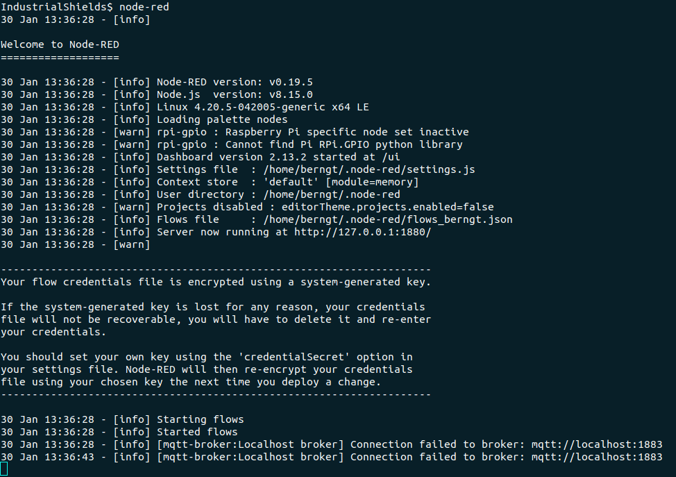
After running the node-red command we are able to go to the localhost:1880/
Type localhost:1880/ in your browser. You will see the Node-RED user interface where we will be able to develop, debug and modify our programs.
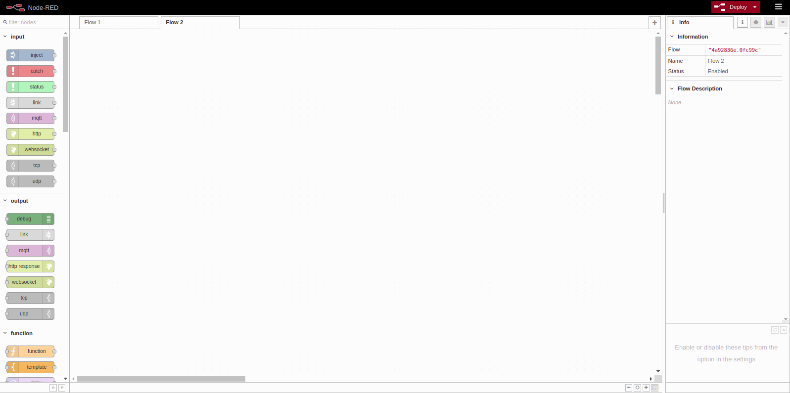
Now we are able to see the different Node-RED blocks at the right site. If you click on a module you will se that in the left site is showed some help documention that will be very useful to understand the block.
CREATING OUR FIRST PROGRAM
Take one MQTT input blog.
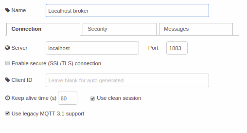
This module will be our MQTT input message from the MQTT broker. Make double click and change the topic for "I". This change will relate the input blog with all the messages that we receive through topic "I". Actually the block have subscribed to "I".
Moreover we must change the server. You will see that you don't have any server created. Create a new server, named and configured as follows. These will be the IP address and the port where the MQTT broker is placed. Take look on the next picture. We have named the server "Localhost broker".
Our MQTT subscription is set properly.
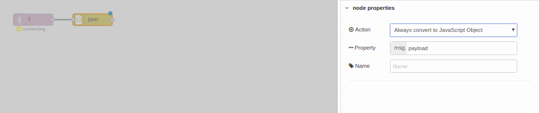
From this block we will receive a JSON string with the following structure:
"{"zone" = 0, "index" = 0 , "value" = 0 }"
Work with string it's not practical. For this reason we have to convert this string to a JavaScript object. Node-RED has one blog dedicated to do this job. This block is named json and we can find it into the functions blocks. Double click to this block. Change the action to "Always convert to JavaScript Object". Now to the output of this message we will have the JavaScript object and will be very east to organised our program.
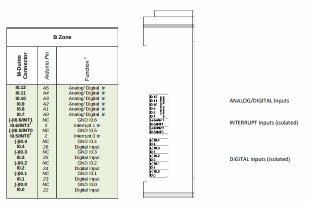
After converting the message from the MQTT "I" topic to a JavaScript we are ready to analyze the object and divided to the different zones and indexes. In this course we just will see an example of M-Duino 21+. So we will have the following input structure.
-
ZONE 0:
- INDEX 0 = I0_0
- INDEX 1 = I0_1
- INDEX 2 = I0_2
- INDEX 3 = I0_3
- INDEX 4 = I0_4
- INDEX 5 = I0_5
- INDEX 6 = I0_6
- INDEX 7 = I0_7
- INDEX 8 = I0_8
- INDEX 9 = I0_9
- INDEX 10 = I0_10
- INDEX 11 = I0_11
- INDEX 12 = I0_12
-
ZONE 1 (M-Duino 42+, M-Duino 38R, M-Duino 38AR+...):
-
-
ZONE 2 (M-Duino 57R+, M-Duino 58+...)
-
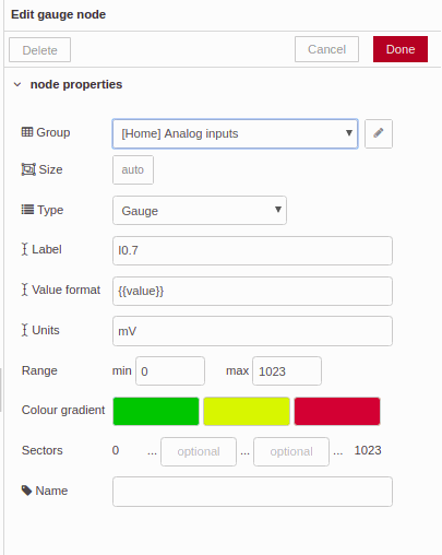
Take a look in the M-Duino 21+ inputs, and you will see that from I0_7 to I0_12 are analog inputs. In fact the values will be representative in a different way, becouse one is digital and the other will be analog (from 0 to 1024). But we will see it later.
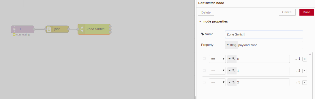
The first split to the object will be the zone.
Node-RED have a block named switch that will be very useful to divide the information an direction it to where we want. So, to filter the zone we will add the switch and with double click we will change the configuration. Add two new conditions. And configured as the following picture. Adding payload.zone we will indicate with part of the object the switch will have to look on in order to classify the message.
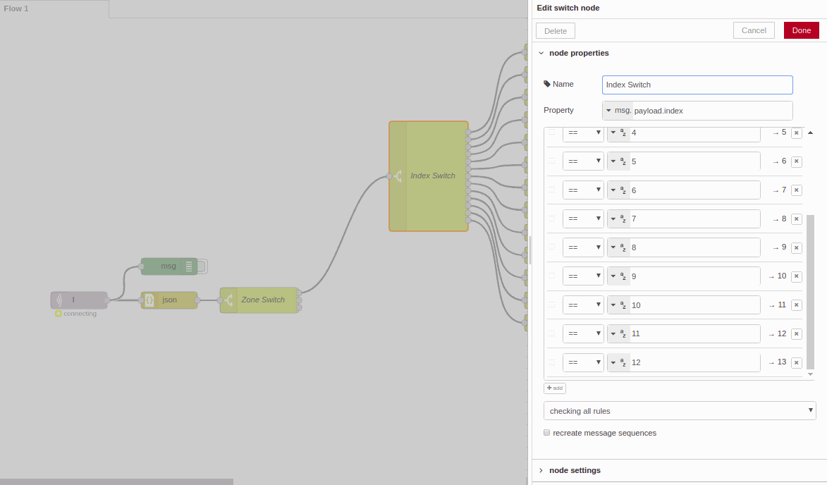
After the first zone switch, we will proceed doing the same for the index.
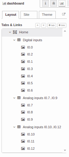
Before placing the final blocks so as to display the values to the dashboard we need to create some groups.
At the right site we have the three different tabs. One to see the debug messages, another for information and another one for the distribution of our dashboard.
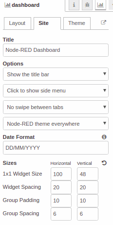
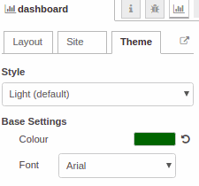
In the Layout site we have distributed the space in three groups, digital inputs and two for analog inputs. When we create the proper dashboard blocks we will decide where to place these block on our dashboard. Apart of that there is other configurations in site and theme tabs that will give a customized look to our dashboard.
So, after analyzed and divided the full message, now we just need to show in our dashboard the real and updated value. In fact we just need to connect the switch block for digital inputs and the gauge block for the analog inputs, you may find this blocks in the dashboard group on the left site.
Node-RED also have the options like a chart for analog signals.
Take a look on the following pictures to have a better understanding.
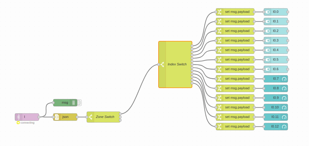
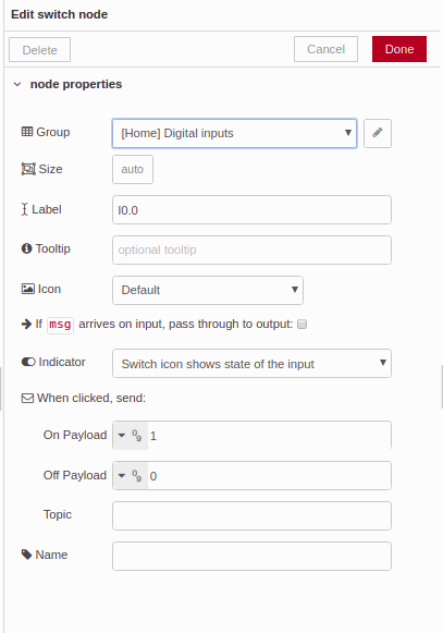
You will have realized that in the last block picture we have placed the msg block. This blog is the debug block. The debug block is very useful to debug our program and follow up every function in order to see how the message flows in our workflow.
Finally we have our logic programmed and we just need to customize our dashboard. Configure the Layout, Site and Theme to give your desired look to your dash board. As example take a look on the following pictures.
Finally the work is done. With the porpoise to test our new program we will have to the mosquitto MQTT broker in our computer and connect the M-Duino to the same network. Next is showed a picture of how the dashboard will be displayed.
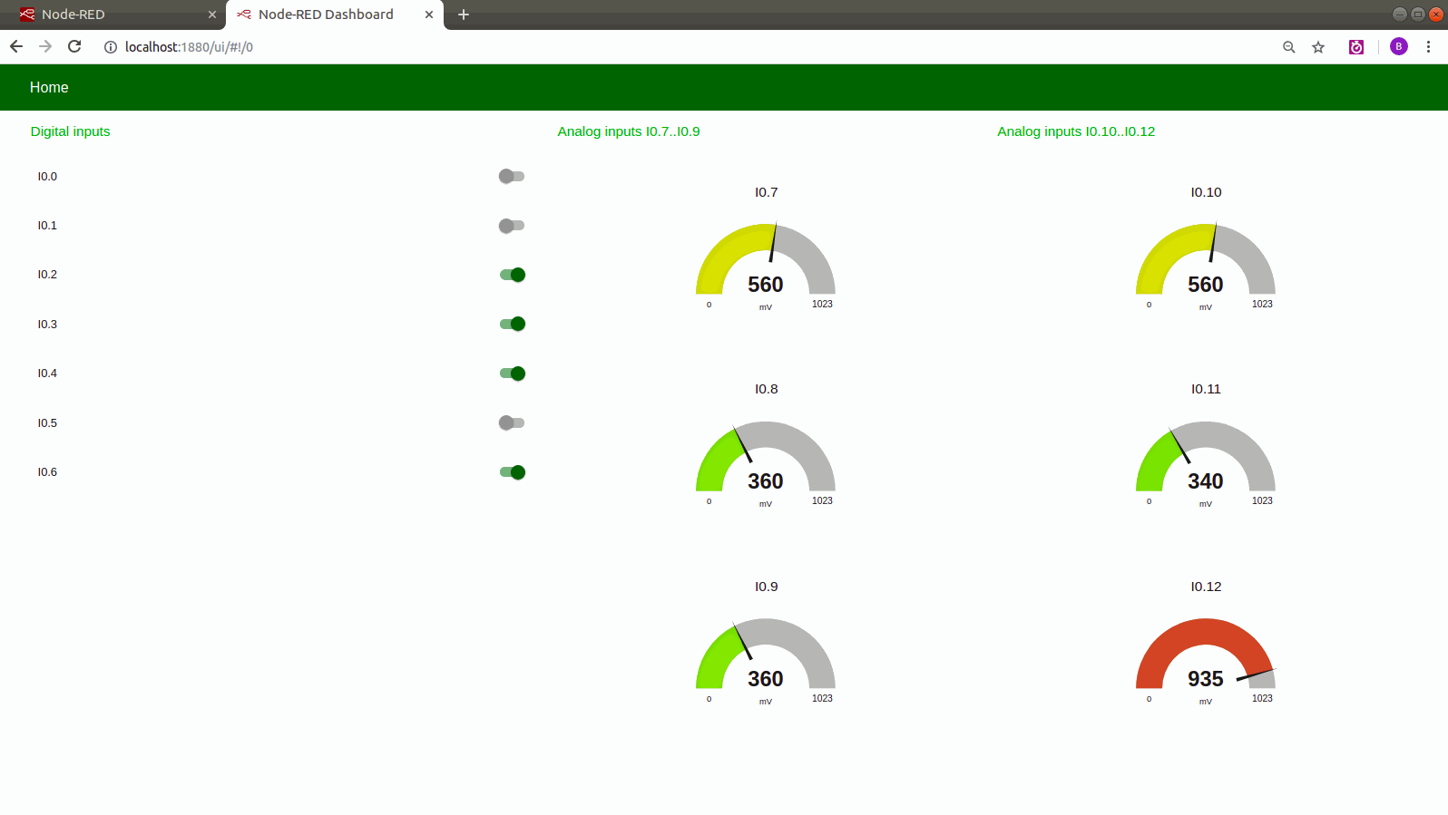
Besides you have a video example of how you will see the dashboard in real time while the inputs values are changing.
How to interact with Outputs
In the chapter #3 is showed how to interact with our outputs of a Industrial Shields PLC. Before start this chapter make sure that you have achieved the steps of the previous chapters. During the course we will be increasing the Node-RED application, so in this one we already have the inputs in the dashboard.
REQUIREMENTS
-
Node-RED and NodeJS installed and running
-
Node-RED-Dashboard installed
-
Mosquito MQTT broker installed and running
-
PLC with the chapter #1 code running
Once the requirements are achieved we will start explaining how the outputs architecture will work.
OUTPUTS ARCHITECTURE
As commented before this course is designed to be used with a M-Duino PLC family. As a example we use a M-Duino 21+.
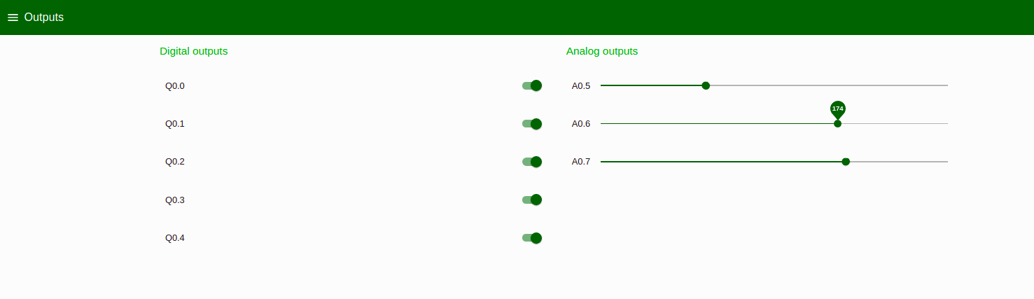
In our M-Duino 21+ we have 8 digital outputs (from Q0_0 to Q0_7), apart of that we know that three of these digital outputs can work as a analog outputs. So in our example will have 5 digital outputs (from Q0_0 to Q0_4) and 3 analog outputs (from A0_5 to A0_7). To extend the Node-RED App to more outputs the procedure is exactly the same.
ADDING A NEW TAB
To have a better organization of our dashboard will be properly to place a new tab where we can control our outputs and not to mix them with our inputs. Obviously this is an example, in you own application you can place the different components regarding your needs.
So, the first part of this chapter we will see how to add a new tab.
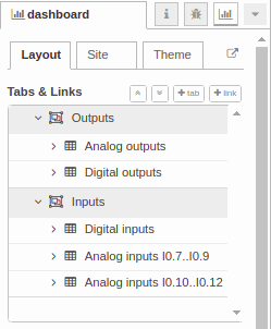
Go to the Node-RED user interface through your browser. At the top right site select the menu and click on flow -- > Add a new flow. Then go to renamed an called Outputs flow.
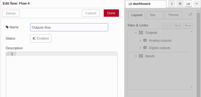
After that an automatic tab will be created. On our Layout we will be able to named and add the new groups. Name your new tab Outputs and add two new groups one called Analog Outputs and other called Digital Outputs.
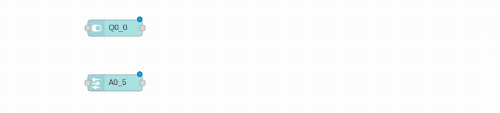
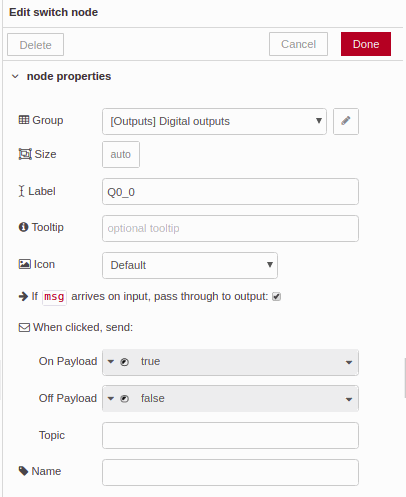
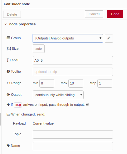
Now we are ready to add the dashboard items. Add a Switch and a Slider. Click on them and named. Select also the group to be placed select Analog outputs for the slider and Digital Outputs for the switch.
*Do not forget to add the topic at the bottom of the Edit switch node. A for Analog Outputs and Q for Digital outputs.
SENDING THE MQTT MESSAGE
Since here we have placed the items to our dash board. So, now it's time to proceed to connect these items to the MQTT broker, in other words send a message with the topic A and Q.
First it's required to relate the switch and slider to the right JS object. Select the Change function and configure it as follows:
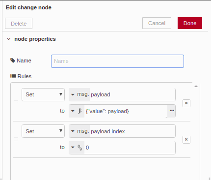
*For every different input we must set the index value. In this case is a "0" because we are configuring the Q0_0.
The change function will add a new content, now we have an index apart of the payload where we have the value of the switch or the analog slider. Besides of the index we need to add the zone. So, add another change function and add the zone parameter. Take look on the next picture:
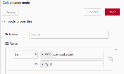
*For every different zone we must set the proper value of the zone. In this case is a "0" because we are configuring the zone 0 (between Q0_0 and A0_7).
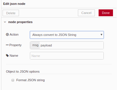
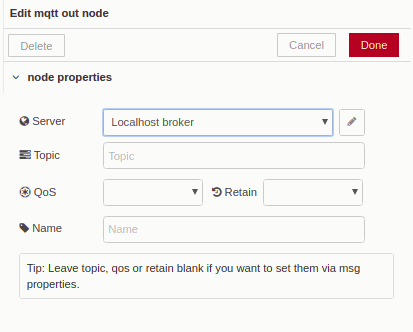
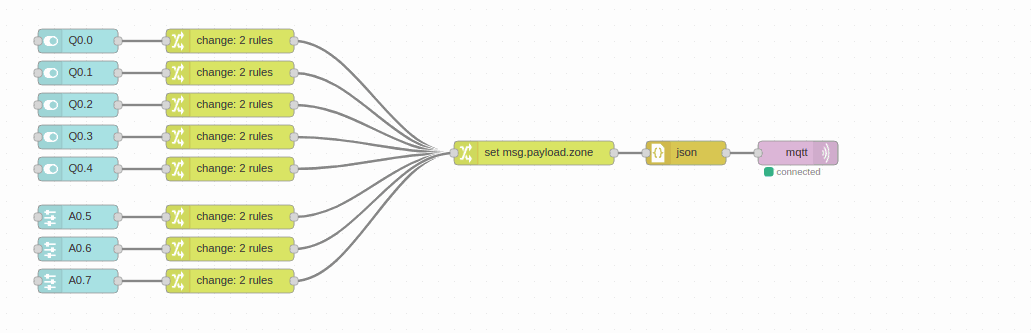
Now we have the JS object set it properly. Now we just must need to create the JSON and send it to the MQTT broker. Take the json function and edited as "Always convert to JSON String". Then add MQTT output function and select the broker. In our case our broker is running in out computer so we select "Localhost broker".
*Remember that we have added the topic into the switch function. We can also defined into the MQTT output function, but then we will have to create two different blocks.
Take a look of the example of how to set the json function and the MQTT output function.
Finally add the entire I/Os that you want to use and place the switch and the sliders where you want using the
Our Node-RED program should look like:
How to configure your Industrial Shields PLC through MQTT
In the chapter #4 is explained how to configure our PLC. Industrial Shields PLC's have a EEPROM where you can set and save some important values that are very relevant for your application.
In this chapter we will follow an imaginary application. Imagine an HVAC (Heating, Ventilating and Air Conditioning) application where you have a a value of humidity and temperature that are your reference point for the system. These values shall be in your EEPROM to not lose it during a power cut and when the PLC restart again just take the last value of the EEPROM to continue with their functionality.
So, in the post we will learn how to use our EEPROM, how to send from the Node-RED values well interpreted by the PLC and how to get values properly interpreted from the PLC to the Node-RED application.
The requirements for this chapter are:
-
Mosquitto or other MQTT broker running
-
Node-RED installed and running
-
M-Duino family PLC
-
Ethernet Network
-
Arduino IDE installed with the proper MQTT library
*Follow the previous chapters to see these steps.
Lets begin with the practical part. At the beginning we will start with the Node-RED application. Our Node-RED app will consist in a Edit Numeric Node where the user will be able to introduce the desired value of our system. So, add two Edit Numeric Node from the dashboard functions.
Our temperature range will be between 15-35ºC (step 0.1 )and our humidity will be between 0-100% (step 1).
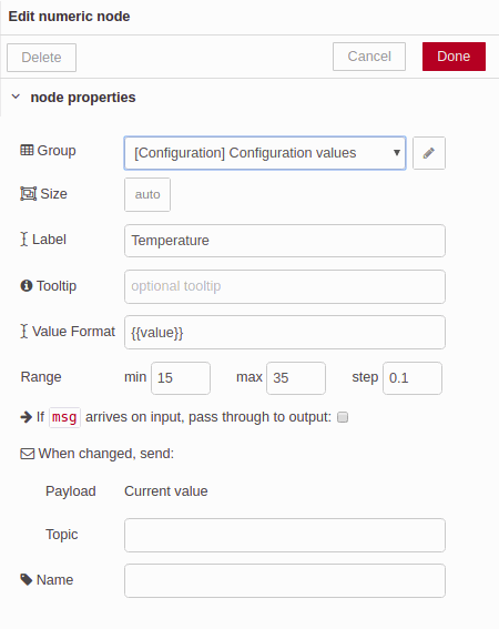
Once the two Edit Numeric Nodes are placed just configure them to showed in the third tab of our dashboard as a configuration tab.
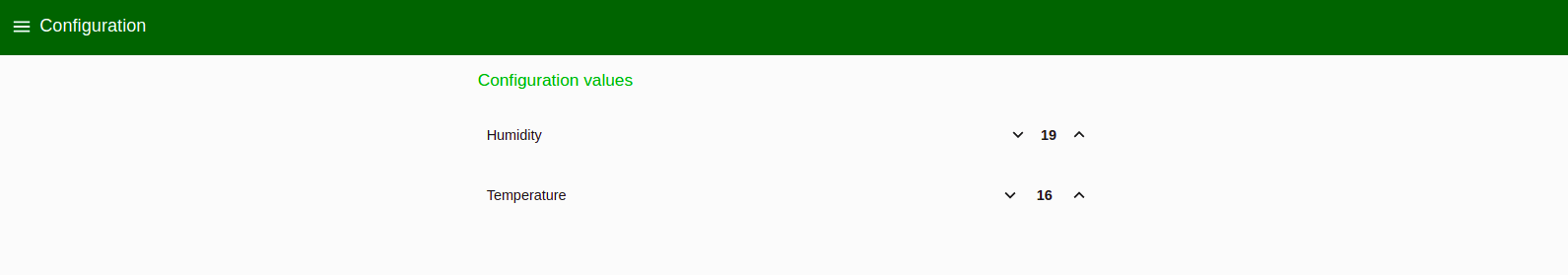
Now our dashboard it looks good. Just lets attend the logic of the application. We want to send this value directly to our MQTT broker. Before to do that we will have to make some changes on this variable to make easier to understand the data in our controller. All Java Scrips variables are 64 bits, this is a problem for us because Arduino Mega or Leonardo used in Industrial Shields PLC just use as a maximum accepted of 32 bits.
In order to change this value we will have to create a new function in our Node-RED workflow.
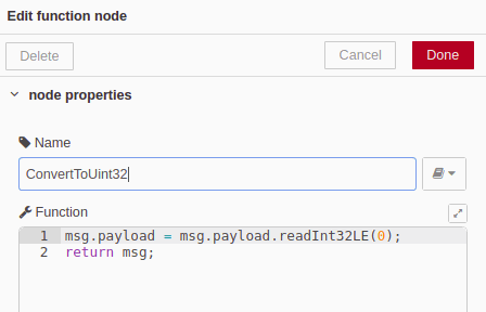
Add a empty function and configured as follows:
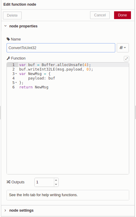
Buffer.allocUnsafe() function return a new uninitialized buffer of the specified size. In our case we want a 4 bytes buffer, take a look on this link to know more about the NodeJS libraries NodeJS buffer information.
Once the buffer is initialized we can proceed to transform out value to a int32_t little endian as our controller can read with any problem. To do that we are using the writeInt32LE(value, offset) function. Read more about in Buffer WriteInt32 function
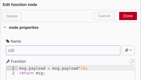
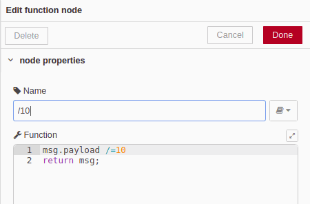
To give more resolution to our system we have decided to multiply the temperature value by 10 in order to treat with centenary numbers in our PLC or controller. So add a short function like that:
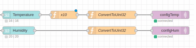
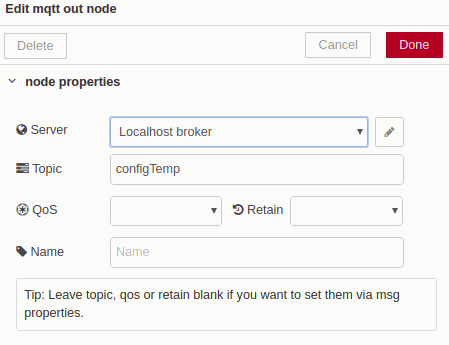
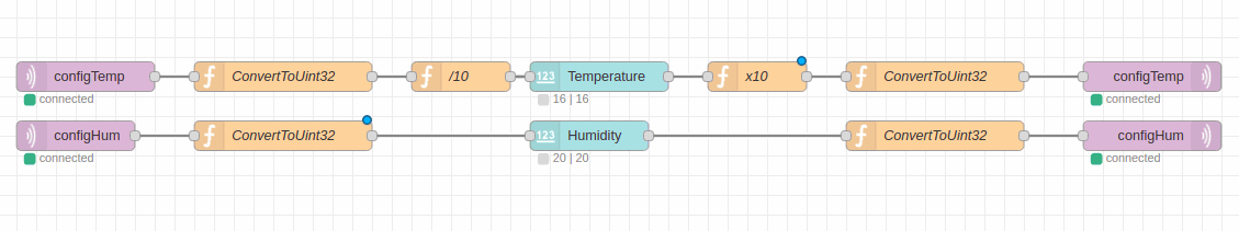
After that our value is ready to be send it. Add a the MQTT send function with the desired topic. At the moment our workflow shall looks like:
Half of the Node-Red is done. As you already know NodeRED nodes actuate when the node suffer a change, then imagine that for some reason you have power cut in your system, the PLC will be working as expected because it has the configured value in their EEPROM, but the system will not know in which value the PLC is working. To solve this issue we will send through the same topic the configured value saved into the PLC EEPROM when the PLC restart their functionality.
How we relate this to our Edit Numeric Node. It just the same as before but in the other way.
Add a receive MQTT function, subscribe the same topic and then add an additional editable function. Configure the function as follows:
As you can see we just use one function here. Take a look on the previous NodeJS links to look how this function works. Basically the function will read a value of 32 bits in little endian and change it for a Java Script value. The value is properly treated for our Node-RED application. Just add a new function to divide the temperature value by 10.
Our work flow shall looks like:
PLC software
Following the Node-RED application we will need a controller that can interact with it. In this second part of the chapter it's showed an example code. The code is a simple example of how to use our EEPROM, structures and MQTT communication protocol.
In our Arduino based PLC we will have a structure made of two int32_t, one for temperature and another for humidity. These values will be system values to set the behavior of the system.
//Configuration structure
typedef struct {
  int32_t temperature;
  int32_t humidity;
} actualConfig_t;

actualConfig_t actualConfig;
In order to get and put values to the EEPROM we will use the EEPROM.h library. The code use two main functions of this library, one is EEPROM.get(eaddress, variable); to get values and EEPROM.put(adress, variable; to safe values.
The other part of the code that is very important is how to read the values from the MQTT. To do that we use the setCallBack function.
mqtt.setCallback(receiveMqttMsg);This function will be called every time than we receive an MQTT message.
void receiveMqttMsg(char* topic, uint8_t* payload, unsigned int len){
    if (strcmp(topic, "configTemp") == 0){
        //Set config to variable
        memcpy(&actualConfig.temperature, payload, len);
        //Print to debug
        Serial.print("Temperature set to: ");
        Serial.println(actualConfig.temperature);
        //Set config to EEPROM
        EEPROM.put(eeAdressTEMP, actualConfig.temperature);
    }
    if (strcmp(topic, "configHum") == 0){
        //Set config to EEPROM
        memcpy(&actualConfig.humidity, payload, len);
        //Print to debug
        Serial.print("Humidity set to: ");
        Serial.println(actualConfig.humidity);
        //Set config to EPROM
        EEPROM.put(eeAdressHUM, actualConfig.humidity);
    }
}
This function will compare the topic to know if the value is a temperature or a humidity using strcmp(topic, "configTemp") == 0
Then will use the memcpy(&adress, data, datalen) to store the data from the MQTT callBack function to our working variable. If in the NodeRED application we didn't modified the data this process will be much more complicated, now we have a little endian int32_t data that is very easy to treat.
Once the data is in our RAM is very easy to store infromation in the EEPROM just using the EEPROM.put() function.
Apart on the code is created a debug function that you can use to know the state of our variables during the workflow.
Below is showed the complete code:
////////////////////////////////////////////////////////////////////////////////////////////////////
//Configuration structure
typedef struct {
  int32_t temperature;
  int32_t humidity;
} actualConfig_t;

#define MQTT_ID "demo"

//including library for MQTT
#include <PubSubClient.h>

//including EEPROM library
#include <EEPROM.h>
//including Ethernet library depending of M-Duino version
#ifdef MDUINO_PLUS
#include <Ethernet2.h>
#else
#include <Ethernet.h>
#endif

actualConfig_t actualConfig;
const byte eeAdressTEMP = 0;
const byte eeAdressHUM = 4;
byte mac[] = { 0xDE, 0xED, 0xBA, 0xFE, 0xFE, 0xAE };
IPAddress ip(10, 10, 11, 2);
IPAddress broker(10, 10, 11, 1);
unsigned port = 1883;
EthernetClient ethClient;
PubSubClient mqtt(ethClient);

void setup(){
    Serial.begin(9600);
    //Set up Ethernet
    Ethernet.begin(mac, ip);
    Serial.print("Local IP: ");
    Serial.println(Ethernet.localIP());
    //Set up MQTT
    mqtt.setServer(broker, port);
    mqtt.setCallback(receiveMqttMsg);
    updateFromEEPROM();
}
////////////////////////////////////////////////////////////////////////////////////////////////////
void loop(){
    if (!mqtt.connected()){
        reconnect();
        if (mqtt.connected()){
            mqtt.publish("actualConfigTemp", (uint8_t*) &actualConfig.temperature);
            mqtt.publish("actualConfigHum", (uint8_t*) &actualConfig.humidity);
        }
    }else{
        mqtt.loop();
    }
//Rest of the logic
}
////////////////////////////////////////////////////////////////////////////////////////////////////
void reconnect(){
    if (mqtt.connect(MQTT_ID)){
        mqtt.subscribe("configTemp");
        mqtt.subscribe("configHum");
    }else{
        //connection fail
        ethClient.stop();
    }
}
////////////////////////////////////////////////////////////////////////////////////////////////////
void receiveMqttMsg(char* topic, uint8_t* payload, unsigned int len){
    if (strcmp(topic, "configTemp") == 0){
        //Set config to variable
        memcpy(&actualConfig.temperature, payload, len);
        //Print to debug
        Serial.print("Temperature set to: ");
        Serial.println(actualConfig.temperature);
        //Set config to EEPROM
        EEPROM.put(eeAdressTEMP, actualConfig.temperature);
    }
    if (strcmp(topic, "configHum") == 0){
        //Set config to EEPROM
        memcpy(&actualConfig.humidity, payload, len);
        //Print to debug
        Serial.print("Humidity set to: ");
        Serial.println(actualConfig.humidity);
        //Set config to EPROM
        EEPROM.put(eeAdressHUM, actualConfig.humidity);
    }
}
////////////////////////////////////////////////////////////////////////////////////////////////////
void updateFromEEPROM(){
    EEPROM.get(eeAdressTEMP, actualConfig.temperature);
    EEPROM.get(eeAdressHUM, actualConfig.humidity);
}
void debug(){
    Serial.println("------------------Debug:-------------------");
    Serial.print("Temp Value:");
    Serial.println(actualConfig.temperature);
    Serial.print("Hum Value:");
    Serial.println(actualConfig.humidity);
}
Below it is attached a video where is showed the functionality of the system. In one side we have the NodeRED dashboard and in the other site we have the serial monitor of Arduino IDE to see how we receive the data. Remember that NodeRED and Mosquitto are running and M-Duino PLC is connected to the same network of the MQTT broker and NodeRED service:
Communications: How to read variables from a Slave device through Modbus TCP/IP
Introduction
The content of the chapter number 5 is focused in controlling an slave device through Modbus TCP/IP. This device is connected in the same network through Ethernet. In this case the device is an M-Duino 21+ using the slave code that is post in our blog.
This is the first requirement to complete and try the new lesson, apart of having the NodeRED installed.
Modbus is a very useful standard that allow us to communicate several devices from different manufacturers in the same network. Besides Modbus TCP/IP is transferred through Ethernet that is one of the most reliable protocols of the market.
In this case we will show how to configure NodeREDin order to control one of the slaves of our system.
Modbus masters normally have 8 main functions:
readCoils();
readDiscreteInputs();
readHoldingRegisters();
readInputRegisters();
writeSingleCoil();
writeSingleRegister();
writeMultipleCoils();
writeMultipleRegisters();
Installation
So, first of all we will need to install the proper library in order to have these functions available in our NodeRED application.
Type in your terminal or command prompt after placing your terminal in the root directory of your NodeRED, nomaly use the .node-red/ :
cd .node-red/npm install node-red-contrib-modbustcp
Now you will see in your NodeRED application that you have two new modbus functions available.
Developing the Application
Often in our installations we have the same two main functionalities to control. Inputs and Outputs. As we have done in the previous chapters we have split the content.
Inputs://///////////////Developing////
Outputs:
Modbus TCP client node. Connects to a Modbus TCP server to write msg.payload to a coil or register.
Function codes currently supported include:
- FC 5: Write Single Coil
- FC 6: Write Single Holding Register
- FC 15: Write Multiple Coils
- FC 16: Write Multiple Holding Registers
After installing the NodeRED library to use the Modbus TCP/IP communication protocol we are able to use their nodes. But before using the main block that will arrange the communication we will have to configure some parameters. We will have to specify the Type and the Address. Type will be the Modbus function and the Address will be the position of the node red array where is our desires I/Os placed.
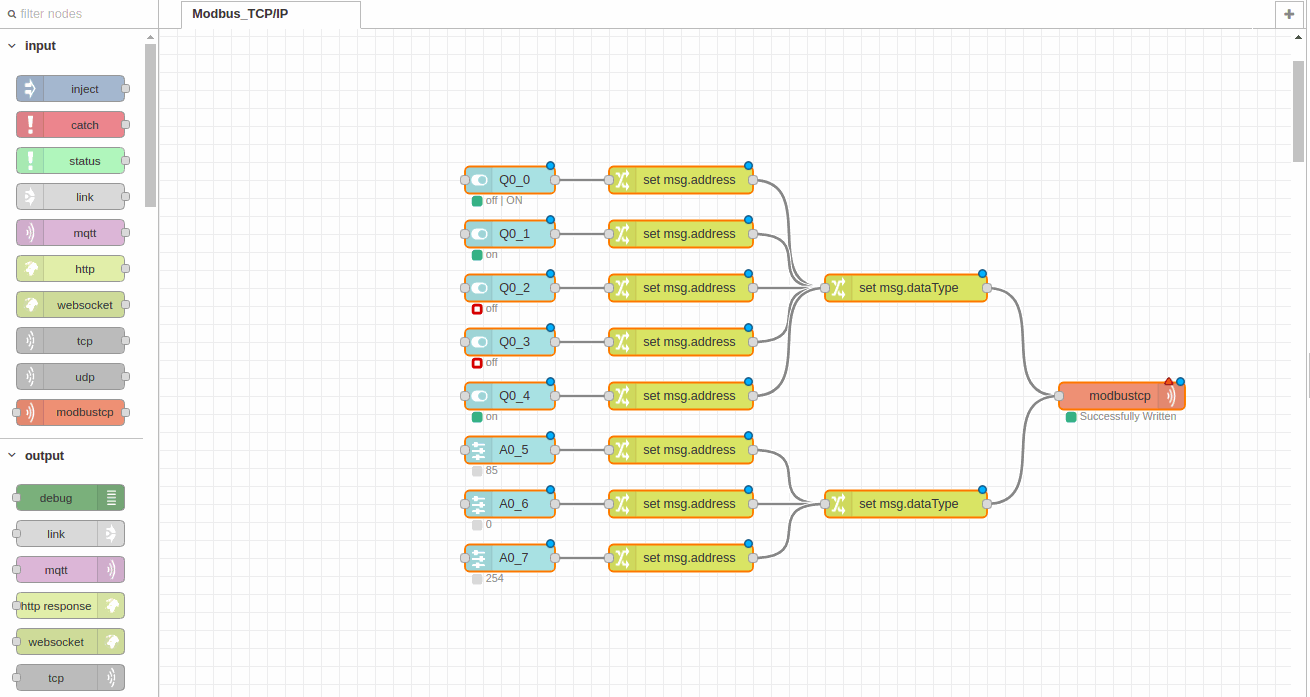
Select one switch and named as you wish. There is no additional configuration for this node.
Then select change block placed on the functions blocks. Type address on the function to give an address to the Jaba Script Object.
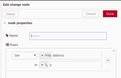
After that our switch will send a message (1/0) and additionally will have an address that is pointing to the right output.
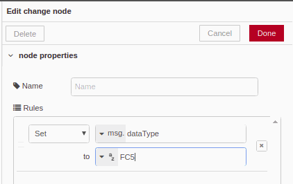
Do the same for the dataType, add a change function type dataType and give the same for all the switches, FC5.
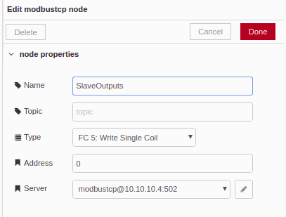
Finally , select the modbustcp block into the outputs nodes. Give a name to the block. Into the configurations, Type and Address are toked for the node if you are not defined before for other nodes. In out case we will defined before to have just one connection opened with our PLC.
So, select any Type and Address. Then configure your Modbus IP Server to the node, in our example we have used 10.10.10.4 IP.
If we do the same process for analog outputs adding sliders instead of switch's we got the entire control of the outputs. The second change node we must select dataType as FC6.
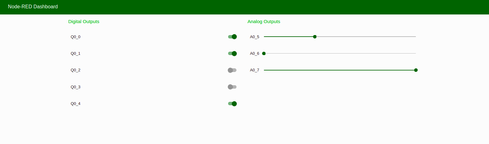
Below is showed the entire output flow and the user interface.
Install NodeRed on Raspberry Pi or Industrial Panel PC based on Linux
Introduction
The content of the chapter number 6 is how to install our NodeRED application to one of our Touchberry Pi or other Panels PC based in Linux. This type of applications are very used for our customers because it's a easy and robust way to have a SCADA touch panel next to the installation. Another point that we will focus during the chapter is how to add the autostart capability, so once we torn on the panel the system will show us directly the NodeRED application.
Installation and Upgrade
Depending which version of Panel PC we will have installed different version of Debian or Ubuntu. Upgrade or install the last version of NodeRED into your system typing in the terminal:
bash <(curl -sL https://raw.githubusercontent.com/node-red/raspbian-deb-package/master/resources/update-nodejs-and-nodered)
Update npm before installing any package using the following comands:
cd ~/.node-red npm outdated npm update
Running NodeRED
To start NodeRED open a new terminal window and type:
node-red-start
*Closing the terminal or ctrl-c does not stop the NodeRED running. It will continue running in the background.
To stop, type:
node-red-stop
Autostart on boot
Probably in your application you will want that the NodeRED start when you turn on your Touchberry Pi. In order to do that we will open the terminal again and type:
sudo systemctl enable nodered.service
and to disable type:
sudo systemctl disable nodered.service
These are the basics to install NodeRED to our Touchberry Pi or other Linux based Industrial Shields panel PC.
If you need additional information about that follow the next link.