
Introduction
Python is a high-level programming language and allows you to do complex things with few lines of code. An example of this can be the purpose of this tutorial. So, in this post, you are going to see an example of how to program the Raspberry PLC to interrupt inputs with Python.
Requirements
The key points you should consider are the following:
Raspberry Family PLC
PLC access: ssh. A tutorial on how to access the device via Linux or Windows can be found in the Raspberry PLC User Guide.
Python installed
Related links
Basics about digital outputs of a Raspberry PLC
Read >>
How to find your perfect industrial PLC
Read >>
External interrupt using capacitive label sensor with Arduino based PLC
Raspberry PLC family products
Read >>
Code Example
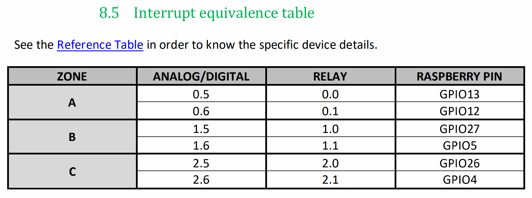
For this example, you need to import the libraries that you can see at the beginning of the code, taking into account that "signal", "sys" and "RPi.GPIO" are essential to work with interrupt inputs in Python with a Raspberry PLC. The INT_GPIO must be the Raspberry GPIO that you are going to configure as an interrupt input, in this case, the 13, which is the INT. If you do not know the mapping between the Raspberry GPIOs and the I/O's of your PLC, you can take a look at these tables, also included in the Datasheet and the User Guide.
To proceed with the explanation, you must know that a signal is a software interrupt delivered to a process. The operating system uses signals to report exceptional situations to a running program.
The first function is the signal_handler, a function that has to be called if a signal triggering event is anticipated, and you can tell the operating system to execute it when that particular type of signal arrives. In this case, this handler makes a GPIO.cleanup() and a sys.exit(0) when it detects a CTRL+C (the command that sends a SIGINT).
The second function is called int_activated_callback and, inside it, you can put the code that you want to be executed when the interruption is activated.
Finally, in the main, there is the GPIO.setmode, configuring it following the GPIOs disposition of the BCM, the GPIO.setup, configuring the GPIO pin to be an input, and GPIO.add_event_detect, that enables an interrupt that calls the "callback" function when the activation edge is FALLING, considering a bouncing time of 1 second (which is the period that no interrupt is going to be activated to avoid signal bouncing). The signal.signal is the function to activate the signal_handler, previously explained. The last infinite loop is simply to test that you can be executing other processes in your code meanwhile the interruption is ready to be activated.
So, if you run this code, it will perform indefinite "Work" prints until the interrupt is activated. When it detects a falling edge on the signal, the previous prints will stop, the interrupt will trigger and you will see the "INT activated" print once, then the "Work" prints will continue until another interruption is activated (always respecting the 1000 ms bounce time).
/*
   Copyright (c) 2019 Boot&Work Corp., S.L. All rights reserved

   This program is free software: you can redistribute it and/or modify
   it under the terms of the GNU Lesser General Public License as published by
   the Free Software Foundation, either version 3 of the License, or
   (at your option) any later version.

   This program is distributed in the hope that it will be useful,
   but WITHOUT ANY WARRANTY; without even the implied warranty of
   MERCHANTABILITY or FITNESS FOR A PARTICULAR PURPOSE.  See the
   GNU Lesser General Public License for more details.

   You should have received a copy of the GNU Lesser General Public License
   along with this program.  If not, see <http://www.gnu.org/licenses/>.
*/
import signal
import sys
import time

import RPi.GPIO as GPIO

INT_GPIO = 13

def signal_handler(sif, frame):
    GPIO.cleanup()
    sys.exit(0)

def int_activated_callback(channel):
    print("INT activated")

if __name__ == '__main__':
    GPIO.setmode(GPIO.BCM)
    GPIO.setup(INT_GPIO, GPIO.IN)
    GPIO.add_event_detect(INT_GPIO, GPIO.FALLING, callback=int_activated_callback,bouncetime=1000)
    signal.signal(signal.SIGINT, signal_handler)
    while 1:
        print ("Work")
        time.sleep(0.1)
The interruption has to be caused by an activation of the input signal, in this case, for a falling edge. To test it, you can connect the sensor GND to the optoisolated GND of the input that you are going to use ((-)IX.5) and the output of the sensor to the interrupt input signal(IX.5/INT). When the digital sensor is activated, you will see the activation of interruption as well. Here you have an example of one of the interrupt inputs of the PLC, with the GND pin and the SIGNAL pin:

How to program Raspberry industrial PLC interrupt inputs with Python