
Index
1. Introduction
2. Requirements
3. Description
4. Implementation
4.1 Hardware configuration
5. Software
6. AT commands
7. Running a server
8. Software
Introduction
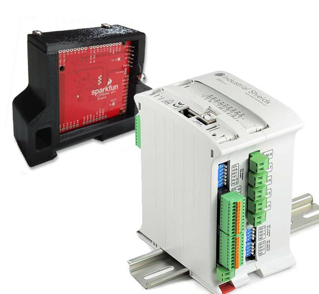
This post it is showed how to connect the ESP8266 WiFi Shield to an Arduino based PLC.
Requirements
Ethernet or 20 I/Os PLC: Ethernet PLC 20 I/Os PLC
Industrial Shields boards: Industrial Shields Boards
ESP8266 Wifi Library: ESP8266 Wifi Library
Description
This WiFi shield is connected using Serial communication, so the Ethernet PLC family is the only one where it can be connected to this module. (As for the 20I/Os Family there is no free Serial communication as they are reserved for the RS-232/RS-485 communication protocols).
The ESP8266 Shield is a cheap and popular WiFi/microcontroller system-on-chip. Furthermore, it can be programmed like a normal controller. Actually, ESP8266 is a serially-controlled WiFi gateway. It can be configured with AT command, so using the Industrial Shields equipment's UART it's possible to communicate to WiFi networks and interact with IoT world over TCP or UDP protocols.
The idea is simple, the ESP8266 is connected to an Ethernet PLC using Serial Communication. The interaction is done using AT Commands, so the PLC sends the AT Commands and the Wifi Shield interprets them.
Implementation
- Hardware configuration
Put the switch selector on hardware serial position (UART HW)
The table below it is shown the hardware connection between both devices:
FOR M-DUINO FAMILY PLCs:
| M-Duino Family PLC | ESP8266 Shield |
| TX1 (Serial 1) | RX |
| RX1 (Serial 1) | TX |
| GND | GND |
| 5V | 5V |
FOR Ardbox FAMILY PLCs:
| M-Duino Family PLC | ESP8266 Shield |
| MISO (pin 14) | RX |
| SCK (pin 15) | TX |
| GND | GND |
| 5V | 5V |
Software
To work with the ESP8266 Wifi Shield it is required a library. This library is supported by the owner of the Wifi Shield.
FOR M-DUINO FAMILY PLCs:
Follow the next steps:
2. Open SparkFunESP8266WiFi.cpp and do the next changes: this sketch is located at:
- C:\Users\{YOUR USER}\Documents\Arduino\libraries\SparkFun_ESP8266_AT_Arduino_Library-master\sr
3. On the first lines on HARDWARE_SERIAL declaration, change the words Serial for Serial1, next is showed a picture of where you must change it:

FOR ARDBOX FAMILY PLCs:
Follow the next steps:
1. Download and install SparkFun ESP8266 WiFi Shield library to your Arduino IDE.
2. Open SparkFunESP8266WiFi.h and do the next changes: this sketch is located at:
- C:\Users\{YOUR USER}\Documents\Arduino\libraries\SparkFun_ESP8266_AT_Arduino_Library-master\srl
3. At the pin definition lines of the sketch (Line 33 and 34):
2. Open SparkFunESP8266WiFi.h and do the next changes: this sketch is located at:
#define ESP8266_SW_RX9
#define ESP8266_SW_TX10
#define ESP8266_SW_TX10
Modify these two lines by:
#define ESP8266_SW_RX14// ESP8266 UART0 RXI goes to Arduino pin 14
#define ESP8266_SW_TX15// ESP8266 UART0 TXO goes
to Arduino pin 15
#define ESP8266_SW_TX15// ESP8266 UART0 TXO goes
AT commands
Once the device is configured and the library is ready it is time to set the ESP8266. Using AT commands it is possible to configure the ESP8266 parameters. Next are showed the main parameters, see more information on the next link:

It is required the proper sketch to use AT commands and communicate with ESP8266 through Serial1 (RX1, TX1). Using the ESP8266_Serial_Passthrough example it's possible to do that. Remember to select on the Serial monitor (Arduino IDE) parameter the Both NL & CR and 9600 baud rate.
Try the different commands to verify that you have good wiring and code. Then configure your network using the AT commant AT+CWJAP="APname","APpass"
FOR M-Duino FAMILY PLCs:
#include <SparkFunESP8266WiFi.h>

void setup(){
  Serial.begin(9600);
  esp8266.begin(9600, ESP8266_HARDWARE_SERIAL);  //esp8266 = Serial1 <- Changed previously in the library
}

void loop(){
  serialPassthrough();
}


void serialPassthrough(){
  while (Serial.available())
    esp8266.write(Serial.read());
  while (esp8266.available())
    Serial.write(esp8266.read());
}
FOR ARDBOX FAMILY PLCs:
#include <SparkFunESP8266WiFi.h>

void setup()
{
  Serial.begin(9600);
  esp8266.begin (9600, ESP8266_SOFTWARE_SERIAL); //esp8266 = SoftwareSerial (MISO(RX),SCK(TX)) <- Changed previously in the library
}

void loop(){
  serialPassthrough();
}

void serialPassthrough(){
  while (Serial.available())
    esp8266.write(Serial.read());
  while (esp8266.available())
    Serial.write(esp8266.read());
}
void serialPassthrough(){ while (Serial.available()) esp8266.write(Serial.read()); while (esp8266.available()) Serial.write(esp8266.read()); }
Running a Server
After configuring your network with AT commands the device is ready to use with its full options.
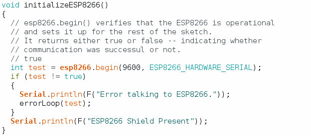
To verify their functionality we will test another code. In this case we will run the ESP8266_Shields_Demo example that can be found into ESP8266 library examples in your Arduino IDE. Before uploading the code we will have to make a little change. Find the initializeESP8266() funtion. Into this function we have to add 9600 and ESP8266_HARDWARE_SERIAL to our esp8266.begin() function. Take a look on the next picture:
After that just select your Industrial Shields unit and the right port that is connected. Upload the sketch and open the Serial Monitor.
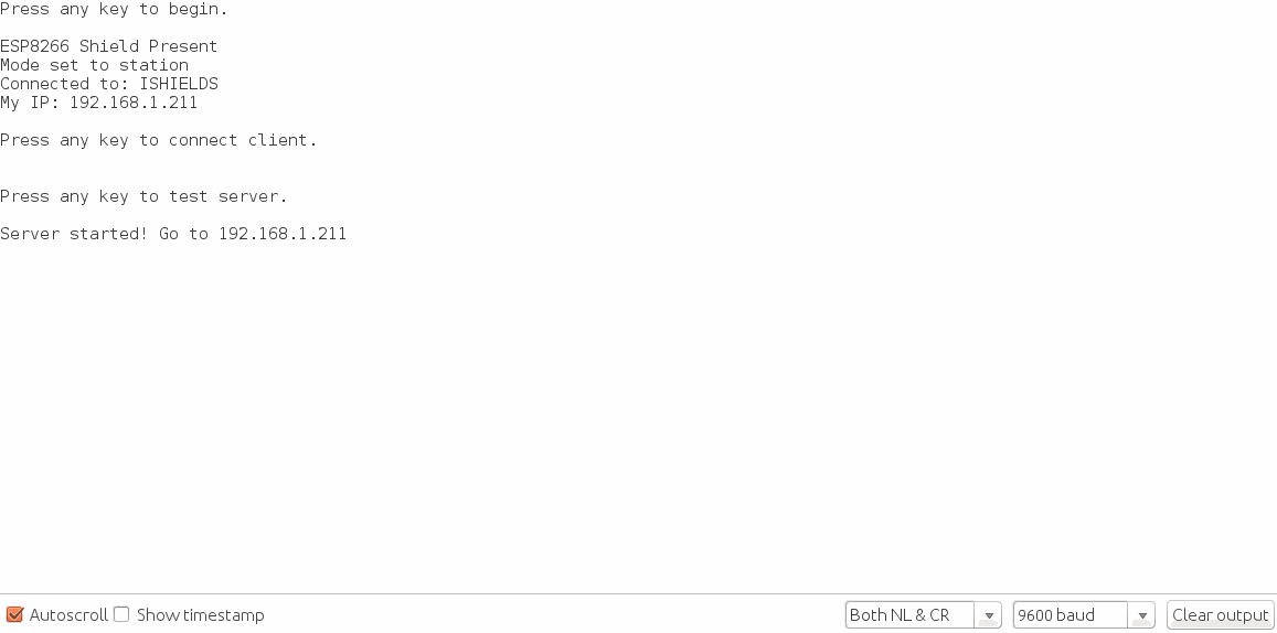
You will see that the program will be asking you to insert a random character to follow up the program. Next is showed two pictures and the code.
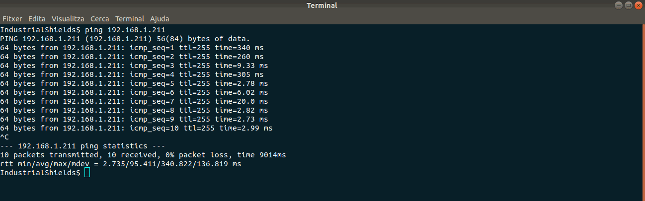
The first picture is showed the Serial Monitor feedback. In the second one is showed a ping from a Linux terminal. As you can see the Wi-Fi shield has initialized the server properly.
Software
//////////////////////
// Library Includes //
//////////////////////
// SoftwareSerial is required (even you don't intend on
// using it).
#include <SoftwareSerial.h>
#include <SparkFunESP8266WiFi.h>

//////////////////////////////
// WiFi Network Definitions //
//////////////////////////////
// Replace these two character strings with the name and
// password of your WiFi network.
const char mySSID[] = "ISHIELDS";
const char myPSK[] = "boot2015SHIELDS";

//////////////////////////////
// ESP8266Server definition //
//////////////////////////////
// server object used towards the end of the demo.
// (This is only global because it's called in both setup()
// and loop()).
ESP8266Server server = ESP8266Server(80);

//////////////////
// HTTP Strings //
//////////////////
const char destServer[] = "example.com";
const String htmlHeader = "HTTP/1.1 200 OK\r\n"
                          "Content-Type: text/html\r\n"
                          "Connection: close\r\n\r\n"
                          "<!DOCTYPE HTML>\r\n"
                          "<html>\r\n";

const String httpRequest = "GET / HTTP/1.1\n"
                           "Host: example.com\n"
                           "Connection: close\n\n";

// All functions called from setup() are defined below the
// loop() function. They modularized to make it easier to
// copy/paste into sketches of your own.
void setup()
{
  // Serial Monitor is used to control the demo and view
  // debug information.
  Serial.begin(9600);
  serialTrigger(F("Press any key to begin."));

  // initializeESP8266() verifies communication with the WiFi
  // shield, and sets it up.
  initializeESP8266();

  // connectESP8266() connects to the defined WiFi network.
  connectESP8266();

  // displayConnectInfo prints the Shield's local IP
  // and the network it's connected to.
  displayConnectInfo();

  serialTrigger(F("Press any key to connect client."));
  clientDemo();

  serialTrigger(F("Press any key to test server."));
  serverSetup();
}

void loop()
{
  serverDemo();
}

void initializeESP8266()
{
  // esp8266.begin() verifies that the ESP8266 is operational
  // and sets it up for the rest of the sketch.
  // It returns either true or false -- indicating whether
  // communication was successul or not.
  // true
  int test = esp8266.begin(9600, ESP8266_HARDWARE_SERIAL);
  if (test != true)
  {
    Serial.println(F("Error talking to ESP8266."));
    errorLoop(test);
  }
  Serial.println(F("ESP8266 Shield Present"));
}

void connectESP8266()
{
  // The ESP8266 can be set to one of three modes:
  //  1 - ESP8266_MODE_STA - Station only
  //  2 - ESP8266_MODE_AP - Access point only
  //  3 - ESP8266_MODE_STAAP - Station/AP combo
  // Use esp8266.getMode() to check which mode it's in:
  int retVal = esp8266.getMode();
  if (retVal != ESP8266_MODE_STA)
  { // If it's not in station mode.
    // Use esp8266.setMode([mode]) to set it to a specified
    // mode.
    retVal = esp8266.setMode(ESP8266_MODE_STA);
    if (retVal < 0)
    {
      Serial.println(F("Error setting mode."));
      errorLoop(retVal);
    }
  }
  Serial.println(F("Mode set to station"));

  // esp8266.status() indicates the ESP8266's WiFi connect
  // status.
  // A return value of 1 indicates the device is already
  // connected. 0 indicates disconnected. (Negative values
  // equate to communication errors.)
  retVal = esp8266.status();
  if (retVal <= 0)
  {
    Serial.print(F("Connecting to "));
    Serial.println(mySSID);
    // esp8266.connect([ssid], [psk]) connects the ESP8266
    // to a network.
    // On success the connect function returns a value >0
    // On fail, the function will either return:
    //  -1: TIMEOUT - The library has a set 30s timeout
    //  -3: FAIL - Couldn't connect to network.
    retVal = esp8266.connect(mySSID, myPSK);
    if (retVal < 0)
    {
      Serial.println(F("Error connecting"));
      errorLoop(retVal);
    }
  }
}

void displayConnectInfo()
{
  char connectedSSID[24];
  memset(connectedSSID, 0, 24);
  // esp8266.getAP() can be used to check which AP the
  // ESP8266 is connected to. It returns an error code.
  // The connected AP is returned by reference as a parameter.
  int retVal = esp8266.getAP(connectedSSID);
  if (retVal > 0)
  {
    Serial.print(F("Connected to: "));
    Serial.println(connectedSSID);
  }

  // esp8266.localIP returns an IPAddress variable with the
  // ESP8266's current local IP address.
  IPAddress myIP = esp8266.localIP();
  Serial.print(F("My IP: ")); Serial.println(myIP);
}

void clientDemo()
{
  // To use the ESP8266 as a TCP client, use the
  // ESP8266Client class. First, create an object:
  ESP8266Client client;

  // ESP8266Client connect([server], [port]) is used to
  // connect to a server (const char * or IPAddress) on
  // a specified port.
  // Returns: 1 on success, 2 on already connected,
  // negative on fail (-1=TIMEOUT, -3=FAIL).
  int retVal = client.connect(destServer, 80);
  if (retVal <= 0)
  {
    Serial.println(F("Failed to connect to server."));
    return;
  }

  // print and write can be used to send data to a connected
  // client connection.
  client.print(httpRequest);

  // available() will return the number of characters
  // currently in the receive buffer.
  while (client.available())
    Serial.write(client.read()); // read() gets the FIFO char

  // connected() is a boolean return value - 1 if the
  // connection is active, 0 if it's closed.
  if (client.connected())
    client.stop(); // stop() closes a TCP connection.
}

void serverSetup()
{
  // begin initializes a ESP8266Server object. It will
  // start a server on the port specified in the object's
  // constructor (in global area)
  server.begin();
  Serial.print(F("Server started! Go to "));
  Serial.println(esp8266.localIP());
  Serial.println();
}

void serverDemo()
{
  // available() is an ESP8266Server function which will
  // return an ESP8266Client object for printing and reading.
  // available() has one parameter -- a timeout value. This
  // is the number of milliseconds the function waits,
  // checking for a connection.
  ESP8266Client client = server.available(500);

  if (client)
  {
    Serial.println(F("Client Connected!"));
    // an http request ends with a blank line
    boolean currentLineIsBlank = true;
    while (client.connected())
    {
      if (client.available())
      {
        char c = client.read();
        // if you've gotten to the end of the line (received a newline
        // character) and the line is blank, the http request has ended,
        // so you can send a reply
        if (c == '\n' && currentLineIsBlank)
        {
          Serial.println(F("Sending HTML page"));
          // send a standard http response header:
          client.print(htmlHeader);
          String htmlBody;
          // output the value of each analog input pin
          for (int a = 0; a < 6; a++)
          {
            htmlBody += "A";
            htmlBody += String(a);
            htmlBody += ": ";
            htmlBody += String(analogRead(a));
            htmlBody += "<br>\n";
          }
          htmlBody += "</html>\n";
          client.print(htmlBody);
          break;
        }
        if (c == '\n')
        {
          // you're starting a new line
          currentLineIsBlank = true;
        }
        else if (c != '\r')
        {
          // you've gotten a character on the current line
          currentLineIsBlank = false;
        }
      }
    }
    // give the web browser time to receive the data
    delay(1);

    // close the connection:
    client.stop();
    Serial.println(F("Client disconnected"));
  }

}

// errorLoop prints an error code, then loops forever.
void errorLoop(int error)
{
  Serial.print(F("Error: ")); Serial.println(error);
  Serial.println(F("Looping forever."));
  for (;;)
    ;
}

// serialTrigger prints a message, then waits for something
// to come in from the serial port.
void serialTrigger(String message)
{
  Serial.println();
  Serial.println(message);
  Serial.println();
  while (!Serial.available())
    ;
  while (Serial.available())
    Serial.read();
}
How to connect a Wifi module to Arduino Based PLC