
This tutorial will explain how to control the digital outputs of an Industrial Shields ESP32 PLC with the Arduino cloud's dashboard widgets. Lets get straight to it.
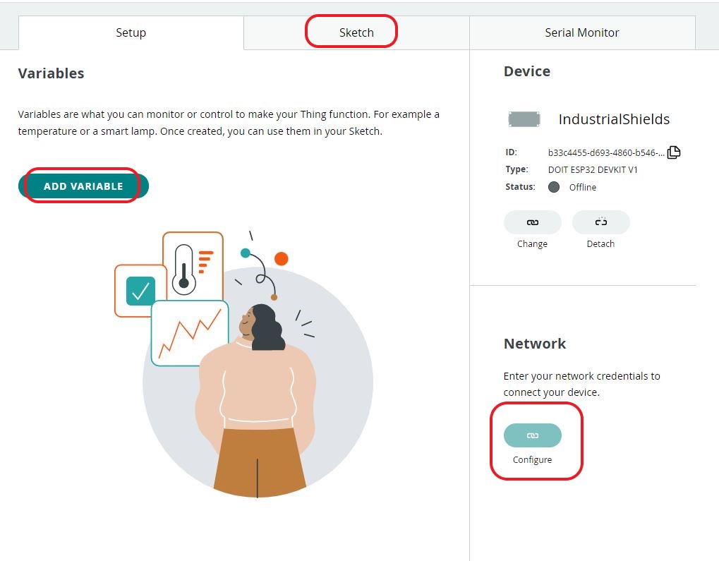
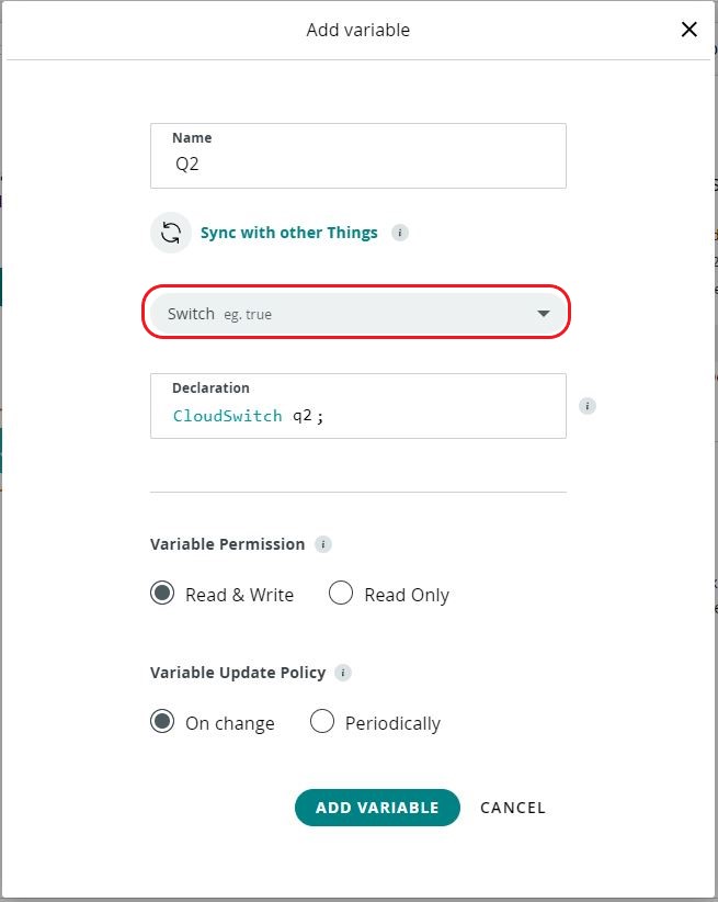
1) Click on Add Variable and look for "switch" from the drop down menu. You might have to de-select the tags in the dropdown. You can name it however you want.
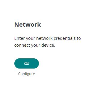
2) Once the variable is created, you can configure the network. You will have to add the SSID and PASSWORD of the network you wish to connect to and the secret key obtained in this tutorial.
After this, you need to click on the sketch tab and then "open full editor".In the web editor, you will see four tabs; You need to copy the contents of "main.ino" (Can be named differently for you) and thingProperties.h to a new arduino project on your PC. You will also need the Secret file contents.

From here on, it is straight forward as a regular Arduino project where you choose the PLC in the board section and code. The codes are shown below:
main.ino
#include "thingProperties.h"
void setup() {
  pinMode(Q0_2, OUTPUT);
  // Initialize serial and wait for port to open:
  Serial.begin(9600);
  // This delay gives the chance to wait for a Serial Monitor without blocking if none is found
  delay(1500);
  // Defined in thingProperties.h
  initProperties();
  // Connect to Arduino IoT Cloud
  ArduinoCloud.begin(ArduinoIoTPreferredConnection);
  /*
     The following function allows you to obtain more information
     related to the state of network and IoT Cloud connection and errors
     the higher number the more granular information you’ll get.
     The default is 0 (only errors).
     Maximum is 4
  */
  setDebugMessageLevel(2);
  ArduinoCloud.printDebugInfo();
}
void loop() {
  ArduinoCloud.update();
  // Your code here
  onQ2Change();
}
/*
  Since Q2 is READ_WRITE variable, onQ2Change() is
  executed every time a new value is received from IoT Cloud.
*/
void onQ2Change()  { ///DIGITAL OUTPUT ON OFF SWITCH
  if (q2 == true) {
    digitalWrite(Q0_2, HIGH);
  }
  else {
    digitalWrite(Q0_2, LOW);
  }
  // Add your code here to act upon Q2 change
}
thingProperties.h
// Code generated by Arduino IoT Cloud, DO NOT EDIT.
#include <ArduinoIoTCloud.h>
#include <Arduino_ConnectionHandler.h>

const char THING_ID[]           = "07c3f5db-b24b-4619-8781-0ce4cc386f24";
const char DEVICE_LOGIN_NAME[]  = "9947c851-3bdb-4eff-84d7-401788196951";
const char SSID[]               = SECRET_SSID;    // Network SSID (name)
const char PASS[]               = SECRET_PASS;    // Network password (use for WPA, or use as key for WEP)
const char DEVICE_KEY[]  = SECRET_DEVICE_KEY;    // Secret device password
void onQ2Change();
CloudSwitch q2;
void initProperties(){
  ArduinoCloud.setBoardId(DEVICE_LOGIN_NAME);
  ArduinoCloud.setSecretDeviceKey(DEVICE_KEY);
  ArduinoCloud.setThingId(THING_ID);
  ArduinoCloud.addProperty(q2, READWRITE, ON_CHANGE, onQ2Change);
}
WiFiConnectionHandler ArduinoIoTPreferredConnection(SSID, PASS);
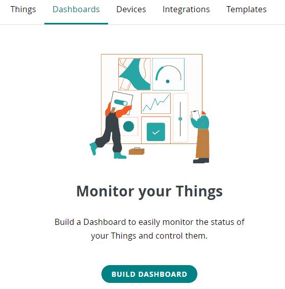
The Dashboard
In this section, a very simple dashboard with just one on-off switch will be shown to control the PLC.
Go to the dashboard tab and click on "BUILD DASHBOARD"
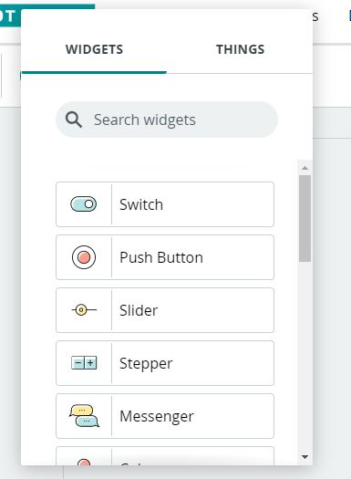
Click on ADD and select the switch.
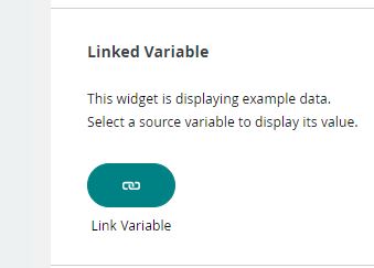
A window will pop up to edit the settings. Here you have to click on the Link Variable button.
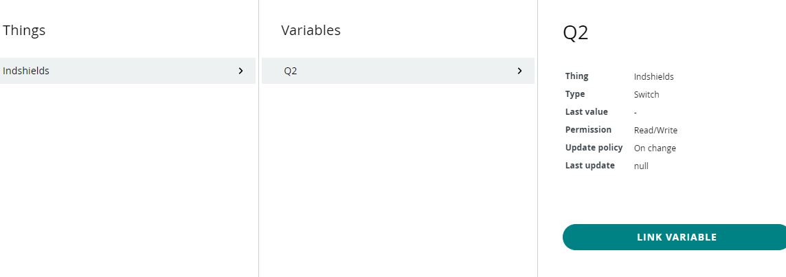
And then link the variable that was created in earlier steps.
After this, we are ready. All we have to do is upload the code to the PLC and make sure that it connects to the configured wifi. You can check the connection status in the serial terminal.
Once done, you can control the digital output of the PLC with the switch created on the dashboard of Arduino cloud.
In the next tutorial, we will see how can get the data of a sensor to the cloud and visualize it.
How to control Digital Outputs with Arduino Cloud