Modbus and Raspberry PLC
This is the first post of the Modbus and Raspberry PLC collection. In them, we will understand and practice with some options the Raspberry PI PLC offers to communicate with Modbus RTU and TCP, using tools such as Node-RED or Python.
This post will be focused on Node-RED, and we will go through everything this browser-based flow editor can provide in Modbus RTU applications.
Requirements
- Raspberry based PLC
- Modbus RTU slave device or Industrial Shields PLC
First steps
To use the Modbus protocol with Node-RED, start by running the editor with this command in the terminal:
$ node-red-start
Then, head to your favorite browser and, depending if you are connected to the Raspberry through SSH or connected to the screen using a micro-HDMI cable, type:
- SSH: PI_PLC_IP_ADDR:1880
- micro-HDMI: 127.0.0.1:1880
Once in the Node-RED flow, we will install the Modbus nodes. Press "Alt+Majus+p" to enter the "Manage Palette" window. There, go to the "Install" tab and search for the node-red-contrib-modbus package. Install it.
After that, we are ready to start dragging nodes to the flow.
Also, make sure the slave device is connected to pins A+ and B- of the Raspberry PLC
Building the flow
The first node will be a "Modbus Write". Double click to configure it, and click on the pencil icon on the "Server" item. Here you will configure the parameters of your Modbus communication:
- Type: Select the "Serial" option, as we are using the Modbus RTU variant in this post.
- Serial Port: Select "/dev/ttySC0" or "/dev/ttySC2", depending on the Raspberry PI PLC version.
- Serial type: "RTU".
- Baud rate: This value will depend on the Modbus slave device, so check the capabilities of the device before choosing the baud rate.
- Unit-Id: This is the identifier of the master device. For convenience, choose "1".
Now choose a name for this configuration and click Update. This defines a specific Modbus configuration, and every node with this settings will perform accordingly. In a more complex system, multiple configurations may be needed, so always make sure you have the correct configuration selected.
Next we will configure the "Modbus Write" node itself:
- Unit-Id: This is the identifier of the slave device, so make sure to match this ID with your slave device ID.
- FC: The Function Code we will be using is the "FC 5: Force Single Coil", but any of the others can be chosen too.
- Address: Type "0".
- Poll Rate: 1 second.
- Server: Select the previous configuration.
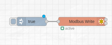
After that, click Done. Now we are almost ready to control a Modbus slave device. Finally, drag an "Inject" node and connect it to the "Modbus Write" node, just like the image below:

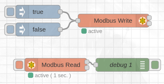
The "Inject" node can also be configured, so double click it and change the msg.payload value from timestamp to a boolean true. Setting the msg.payload to a boolean false is equivalent to setting the coils / registers to 0 instead of 1.
With that, every time you press the inject node, a Modbus message will be sent through pins A+ and B+ and the slave will act upon.
Reading is also very simple. Drag a "Modbus Read" node and configure if like so:
- Unit-Id: The same identifier as in the "Modbus Write" node.
- FC: Select "FC 1: Read Coil Status".
- Address: Type "0".
- Quantity: Type "1".
- Poll Rate: 1 second.
- Server: Select the previous configuration.
Finally, connect a "Debug" node in the first output of the "Modbus Read" node and Deploy your changes and in the Debug panel you will see how the first element of the list changes.

[{"id":"5e1ff7e5bdc20aad","type":"tab","label":"Flow 1","disabled":false,"info":"","env":[]},{"id":"bf0737313ed47579","type":"modbus-write","z":"5e1ff7e5bdc20aad","name":"","showStatusActivities":true,"showErrors":true,"showWarnings":true,"unitid":"31","dataType":"Coil","adr":"0","quantity":"1","server":"d71fcab96da43404","emptyMsgOnFail":false,"keepMsgProperties":false,"delayOnStart":false,"startDelayTime":"","x":660,"y":300,"wires":[[],[]]},{"id":"ecf9141ee03c86bc","type":"inject","z":"5e1ff7e5bdc20aad","name":"","props":[{"p":"payload"},{"p":"topic","vt":"str"}],"repeat":"","crontab":"","once":false,"onceDelay":0.1,"topic":"","payload":"true","payloadType":"bool","x":510,"y":280,"wires":[["bf0737313ed47579"]]},{"id":"d3759149be3b0b7e","type":"inject","z":"5e1ff7e5bdc20aad","name":"","props":[{"p":"payload"},{"p":"topic","vt":"str"}],"repeat":"","crontab":"","once":false,"onceDelay":0.1,"topic":"","payload":"false","payloadType":"bool","x":510,"y":320,"wires":[["bf0737313ed47579"]]},{"id":"8f43e9aa567f6f3c","type":"modbus-read","z":"5e1ff7e5bdc20aad","name":"","topic":"","showStatusActivities":false,"logIOActivities":false,"showErrors":false,"showWarnings":true,"unitid":"31","dataType":"Coil","adr":"0","quantity":"1","rate":"1","rateUnit":"s","delayOnStart":false,"startDelayTime":"","server":"d71fcab96da43404","useIOFile":false,"ioFile":"","useIOForPayload":false,"emptyMsgOnFail":false,"x":530,"y":400,"wires":[["d2d923f66ea77a31"],[]]},{"id":"d2d923f66ea77a31","type":"debug","z":"5e1ff7e5bdc20aad","name":"debug 1","active":true,"tosidebar":true,"console":false,"tostatus":false,"complete":"false","statusVal":"","statusType":"auto","x":680,"y":400,"wires":[]},{"id":"d71fcab96da43404","type":"modbus-client","name":"ModbusRTU","clienttype":"simpleser","bufferCommands":true,"stateLogEnabled":false,"queueLogEnabled":false,"failureLogEnabled":true,"tcpHost":"127.0.0.1","tcpPort":"502","tcpType":"DEFAULT","serialPort":"/dev/ttySC0","serialType":"RTU","serialBaudrate":"38400","serialDatabits":"8","serialStopbits":"1","serialParity":"none","serialConnectionDelay":"100","serialAsciiResponseStartDelimiter":"0x3A","unit_id":1,"commandDelay":1,"clientTimeout":1000,"reconnectOnTimeout":true,"reconnectTimeout":2000,"parallelUnitIdsAllowed":true,"showWarnings":true,"showLogs":true}]
Want to know more about Modbus?
Check out the other posts from the collection here:
Introduction to Modbus and Raspberry PLC. Part 1